Oversampled filter bank for subband processing

a filter bank and subband processing technology, applied in the field of filter banks, can solve the problems of severe constraining the kind of processing, unsuitability for applications, and suffering from aliasing between subbands, and achieve the effects of reducing the prototype filter order, improving temporal response, and substantially reducing the aliasing between subbands

Inactive Publication Date: 2005-09-20
VERANCE
View PDF5 Cites 102 Cited by
  • Summary
  • Abstract
  • Description
  • Claims
  • Application Information

AI Technical Summary

Benefits of technology

[0014]The present invention relates to an oversampled filter bank structure for subband processing that can be implemented using popular fast filter banks, such as FFT and cosine-modulated filter banks. Advantageously, aliasing between subbands is substantially reduced, thus allowing independent processing of the subband signals. Also, the filter design criteria is significantly relaxed, thus resulting in a lower prototype filter order, better temporal response and higher stop band rejection.
[0029]In an optional embodiment, a digital filter apparatus provides 4× oversampling to further reduce the likelihood of aliasing. An input signal is processed in four parallel paths, three of which include frequency shifters for providing shifts of π / M, π / 2M, and −π / 2M radians, and one of which includes a delay for compensating for a processing time of the frequency-shifters.

Problems solved by technology

While the efficiency of these filter banks makes them suitable for many signal processing applications, they suffer from aliasing between the subbands.
However, this cancellation property severely constrains the kind of processing that can be introduced by the subband processors SB(0), .
This makes the use of such filter banks unsuitable for applications such as subband equalizers or noise shaper.
However, this decreases the temporal resolution of the filter banks as well as the computational efficiency since additional calculations are required.
However, aliasing is still present between the subbands unless the oversampling ratio approaches the number of subbands M. This approach also is not computationally efficient.

Method used


Image

  • Oversampled filter bank for subband processing
  • Oversampled filter bank for subband processing
  • Oversampled filter bank for subband processing

Examples


Embodiment Construction

[0059]The present invention relates to a filter bank for use in digital signal processing to prepare a signal for subband processing.

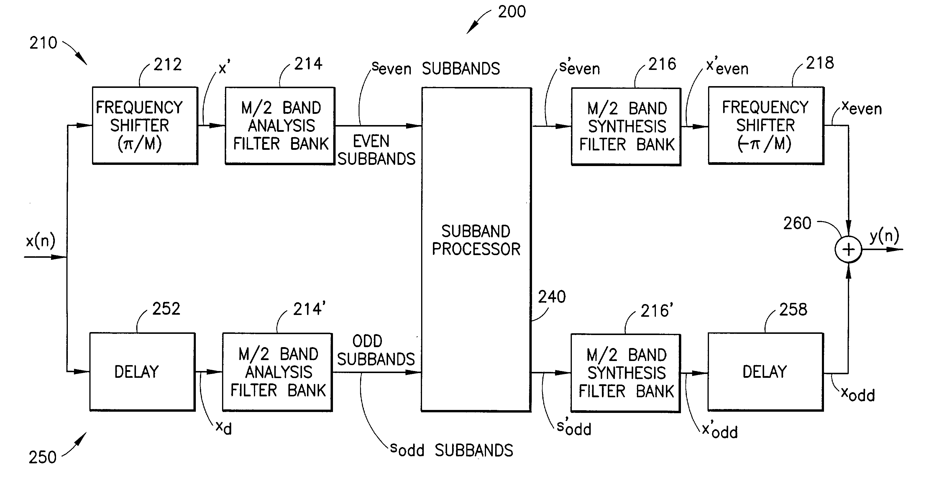
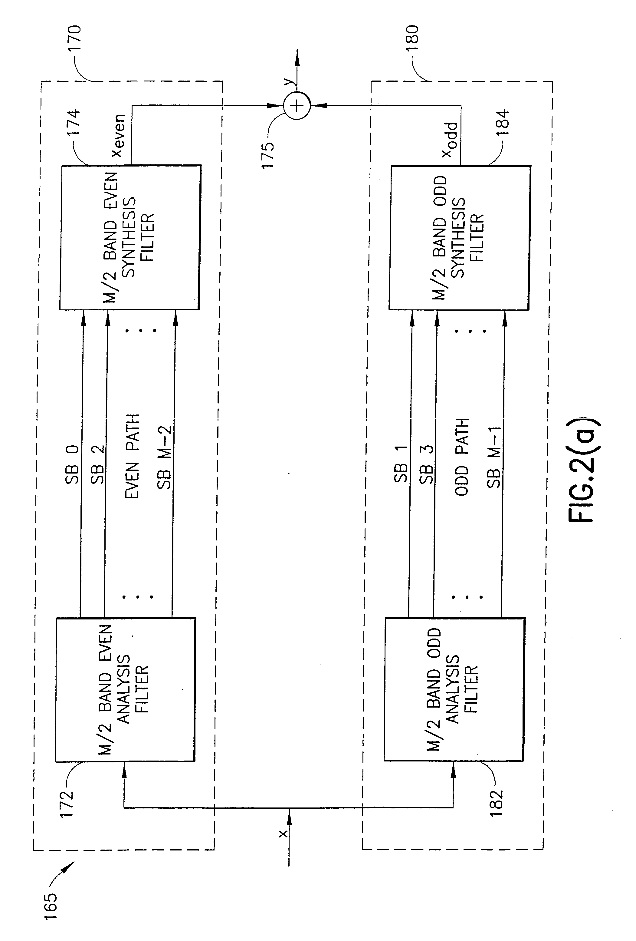
[0060]FIG. 2(a) illustrates a generalized filter structure with 2×-oversampled filter banks in odd and even subband paths in accordance with the present invention.

[0061]The filter apparatus 165 processes the input signal x(n) in an even subband path 170 and an odd subband path 180. The even path 170 includes an M / 2-band even subband oversampled analysis filter bank 172, and an M / 2-band even subband oversampled synthesis filter bank 174. Similarly, the odd path 180 includes an M / 2-band odd subband oversampled analysis filter bank 182, and an M / 2-band odd subband oversampled synthesis filter bank 184.

[0062]A subband processor can be provided between the filters 172 and 174, and between the filters 182 and 184.

[0063]A combiner 175 receives the output of the filter 174, xeven, and the output of the filter 184, xodd, to provide the output signal y(n).

[0064]...


PUM


Abstract

An oversampled filter bank structure that can be implemented using popular and efficient fast filter banks to allow subband processing of an input signal with substantially reduced aliasing between subbands. Even subbands (SB0, SB2, SB4, . . . ) of an input signal (x(n)) are frequency-shifted (212, 1012, 1012′, 1012″) prior to analysis filtering (214, 214′, 214″) at a 2× oversampled filter bank, subband processing (240, 240′, 240″), and synthesis filtering (216, 216′, 216″). A subsequent frequency-shift (218, 218′) returns the even subbands to their original band positions. The odd subbands (SB1, SB3, SB5, . . . ) are delayed (252) to compensate for the processing time of the frequency shifting. Separate analysis (214, 214′) and synthesis (216, 216′) filter banks may be provided for the even and odd subbands, or common complex analysis (284) and synthesis (286) filter banks may be used. In another embodiment, the subbands are processed in four subband paths (Paths 0, 1, 2, 3), and 4× oversampling is used. A filter bank structure (1400) for 2-D data is also provided.

Description

[0001]This application is a 35 U.S.C. 371 application of PCT / US99 / 28343, filed on Nov. 30, 1999.BACKGROUND OF THE INVENTION[0002]The present invention relates to a filter bank for use in digital signal processing, and in particular, to an efficient filter bank structure that uses oversampling and separate odd and even subband processing paths to reduce aliasing between subbands.[0003]The digital filter bank is an enabling technology for modern audio and video processing systems, and, more recently, digital data communication systems such as Orthogonal Frequency-Division Multiplexing (OFDM). FIG. 1 illustrates a typical conventional filter bank structure. A circuit 100 processes an input digital signal x(n) in N separate paths. An analysis filter bank 120 includes respective analysis filters that decompose and transform the input signal x(n) into its frequency-domain subband components xb(0), . . . ,xb(N−1) according to respective transfer functions H(0), H(1) . . . H(i), . . . H(N−1...

Claims


Application Information

Patent Timeline
Patent Type & Authority Patents(United States)
IPC IPC(8): H04B1/10H03H17/02
CPCH03H17/0266
Inventor WONG, DOUGLAS
Owner VERANCE
Why Eureka
Try Eureka