
Shaft clamping arrow rest

a technology for clamping arrows and arrows, which is applied in the direction of compressed gas guns, white arms/cold weapons, weapons, etc., can solve the problems of a large noise, a large noise, and a large amount of nois

Inactive Publication Date: 2005-09-27
AFSHARI ABBAS BEN
View PDF14 Cites 19 Cited by
  • Summary
  • Abstract
  • Description
  • Claims
  • Application Information

AI Technical Summary

Benefits of technology

The solution ensures the arrow shaft remains securely held during draw and launches without noise or damage, allowing for silent operation and improved accuracy by minimizing contact with the arrow rest during flight.

Problems solved by technology

Such fall-away arrow rests, while attempting to resolve some of the problems caused by arrow rests, do not address a significant disadvantage of all arrow rests.
Because of the jerking force of such a maneuver, the archer is often unable to maintain the shaft of the arrow on the arrow rest.
As the arrow falls, it may impact the riser of the bow generating a noise that can startle game.
In a hunting setting, noise is a major factor in the ability to stalk an animal.
As most hunters will attest, the “clanking” of the shaft of a falling arrow against the riser is sure to startle most game causing the animal to flee.
Even with the Muzzy device, however, an archer is not likely to be able to move through underbrush with a loaded arrow without the arrow falling from the arrow rest.
The bristles, however, tend to tear the fletching from the shaft of the arrow.

Method used


Image

  • Shaft clamping arrow rest
  • Shaft clamping arrow rest
  • Shaft clamping arrow rest

Examples


Embodiment Construction

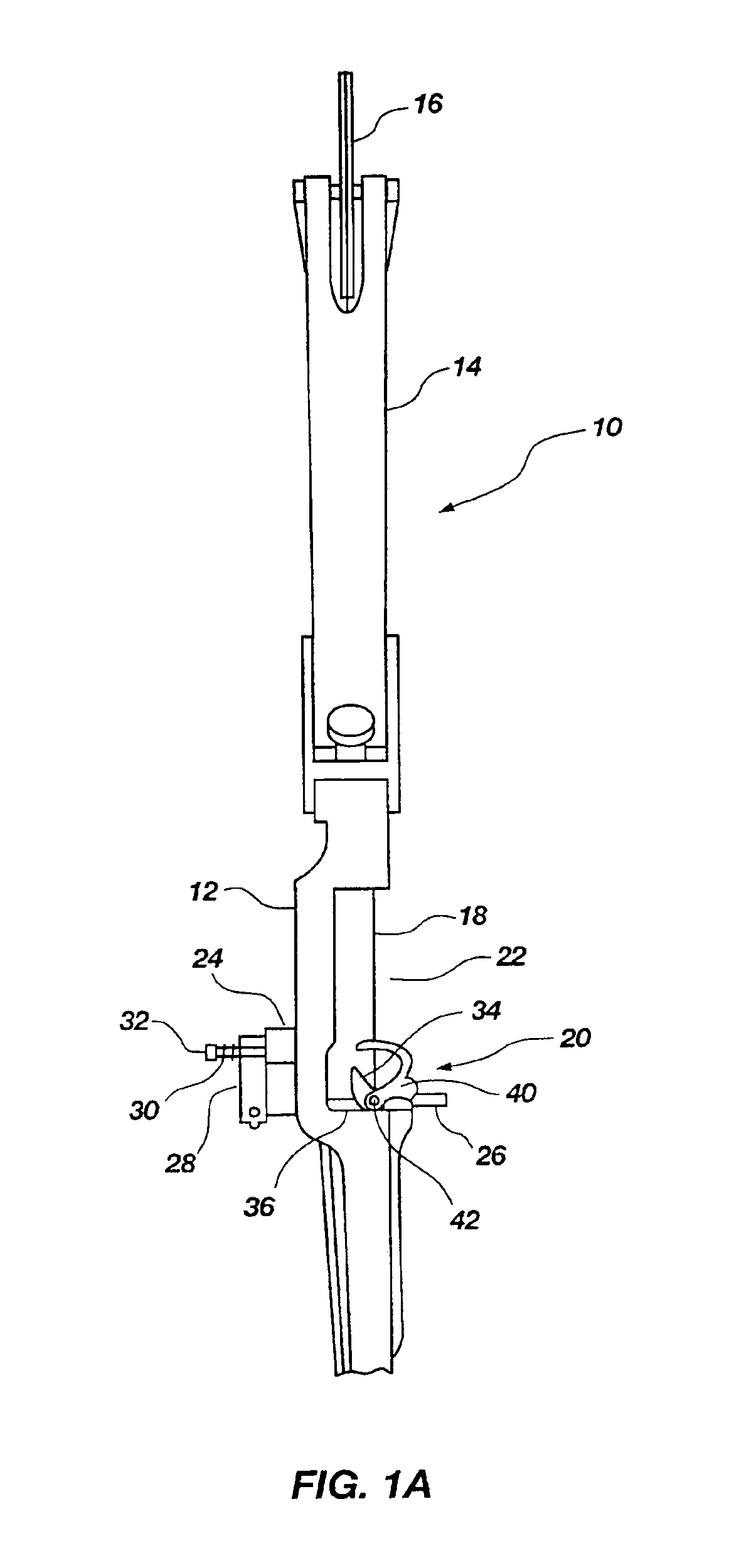
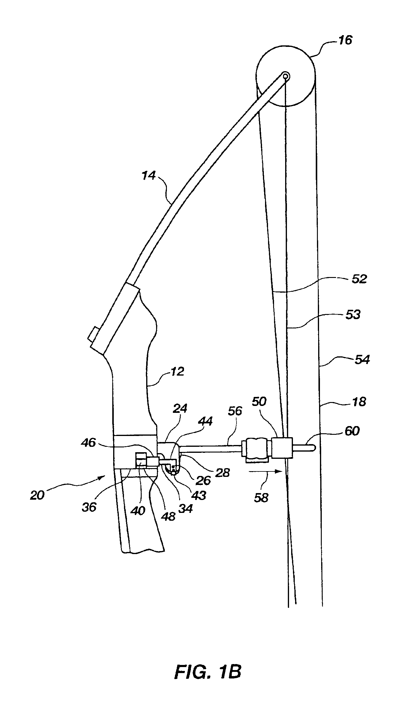
[0046]Referring to the drawings, FIG. 1A illustrates a compound bow, generally indicated at 10, to which an arrow rest assembly, generally indicated at 20 is, is attached. The compound bow comprises a typical bow assembly having a riser 12 and an upper limb 14 to which an upper pulley or cam is rotatably attached. A cable 18 is provided for launching an arrow (not shown). It should be noted, however, that while the bow 10 is illustrated as having a particular configuration, the arrow rest 20 of the present invention could be adapted to be attached to and function with any compound bow in the art as well as those developed in the future.

[0047]The riser 12 of the bow 10 defines a laterally offset portion 22 through which the arrow is launched. The offset portion 22 allows the cable 18 to be in generally vertical alignment with the limb 14 and the remainder of the riser 12 while providing a channel or window to allow positioning of an arrow therein while maintaining proper alignment of...


PUM


Abstract

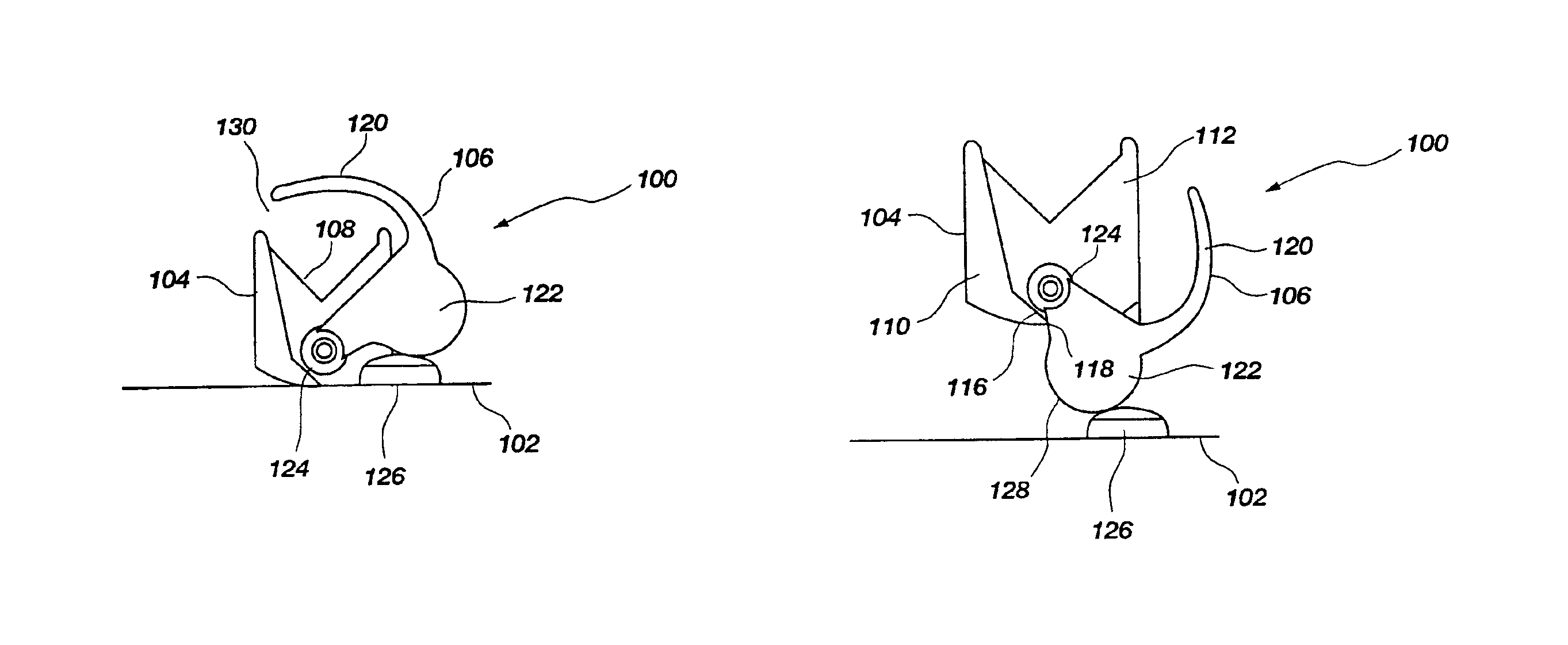
An arrow rest comprises an arrow rest support arm pivotally mounted to the riser of a bow. The support arm is coupled to a cable guide of the bow through linkage that causes the support arm to rise relative to the riser of the bow as the cable is drawn to launch an arrow. As the cable is released to launch an arrow, the arrow rest drops to allow the fletching to pass the arrow rest without contact. In addition, as the arrow rest moves from a first resting position to a second pre-launch position and back again, a clamping mechanism grasps the shaft of the arrow when the support arm is in the resting position. As the support arm moves to the pre-launch position, the clamping mechanism releases the shaft of the arrow so that the arrow can be freely launched from the support arm without interference from the clamping mechanism.

Description

CROSS-REFERENCED TO RELATED APPLICATIONS[0001]This application is a continuation of and claims priority to co-pending U.S. patent application Ser. No. 10 / 121,123, filed on Apr. 11, 2002, now U.S. Pat. No. 6,681,753.BACKGROUND[0002]1. Field of the Invention[0003]The present invention relates to an apparatus for supporting the shaft of an arrow when launched from an archery bow. More particularly, the present invention relates to an arrow rest that can move from a first, resting position to a second ready position as the sting of the bow is drawn to a firing position. In the resting position, the arrow rest holds the shaft of the arrow relative to the arrow rest. In the ready position, the arrow rest supports the shaft of the arrow but no longer clamps the shaft of the arrow to allow the arrow to freely launch from the arrow rest.[0004]2. Description of the Prior Art[0005]Over the past few decades, the interest in the sport of archery in the United States has significantly increased. ...

Claims


Application Information

Patent Timeline
Patent Type & Authority Patents(United States)
IPC IPC(8): F41B5/22F41B5/00
CPCF41B5/143
Inventor AFSHARI, ABBAS BEN
Owner AFSHARI ABBAS BEN
Learn More