
Computer server mounting apparatus

a technology for mounting equipment and servers, applied in the direction of washstands, dismountable cabinets, lighting support devices, etc., can solve the problems of unreliable means by which slides are mounted to the rack structure in such mounting systems, time-consuming installation process, screwdriver use,

Inactive Publication Date: 2005-09-27
JONATHAN ENGINEERED SOLUTIONS
View PDF17 Cites 180 Cited by
  • Summary
  • Abstract
  • Description
  • Claims
  • Application Information

AI Technical Summary

Benefits of technology

[0013]In accordance with another aspect of the present invention, a mounting apparatus is provided, comprising a slide having a stationary portion and a telescoping portion. The telescoping portion is slidably attached to the stationary portion and has one or more mounting slots formed therein. A chassis is also provided having one or more mounting protrusions extending therefrom. The mounting protrusions are engageable in the mounting slots to support the chassis on the slide. A lock is provided at one of the mounting slots. The lock is selectively engageable with an associated one of the mounting protrusions to prevent removal of the mounting protrusion from the slot.
[0014]In accordance with another aspect of the present invention, a mounting apparatus is provided, comprising a slide having a stationary portion and a telescoping portion. The telescoping portion is slidably attached to the stationary portion and has one or more mounting slots formed therein. A chassis is also provided having one or more mounting protrusions extending therefrom. The mounting protrusions are engageable in the mounting slots to support the chassis on the slide. A lock arm is provided at one of the mounting slots. The lock arm flexes away from the mounting slot to allow passage of an associated one of the mounting protrusions through the slot in a first direction, and abuts the mounting protrusion to prevent passage of the mounting protrusion through the slot in a second opposite direction.

Problems solved by technology

As a result, the installation process was typically time consuming and required the use of screwdrivers, wrenches, or other tools.
However, these toolless mounting systems, while more convenient than previous mounting systems, have so far proved unsatisfactory.
In particular, the means by which the slides are mounted to the rack structure in such mounting systems has proven to be unreliable, as described more fully hereinbelow.

Method used


Image

  • Computer server mounting apparatus
  • Computer server mounting apparatus
  • Computer server mounting apparatus

Examples


Embodiment Construction

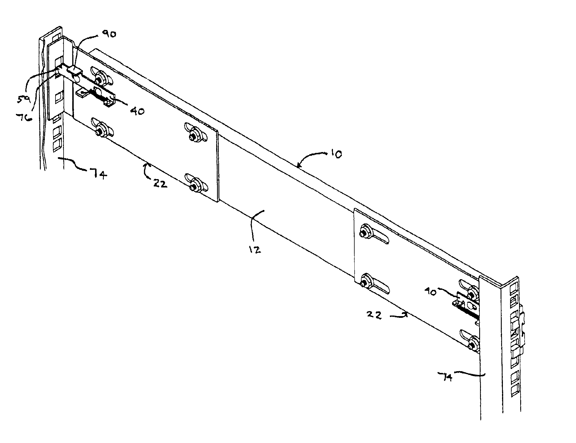
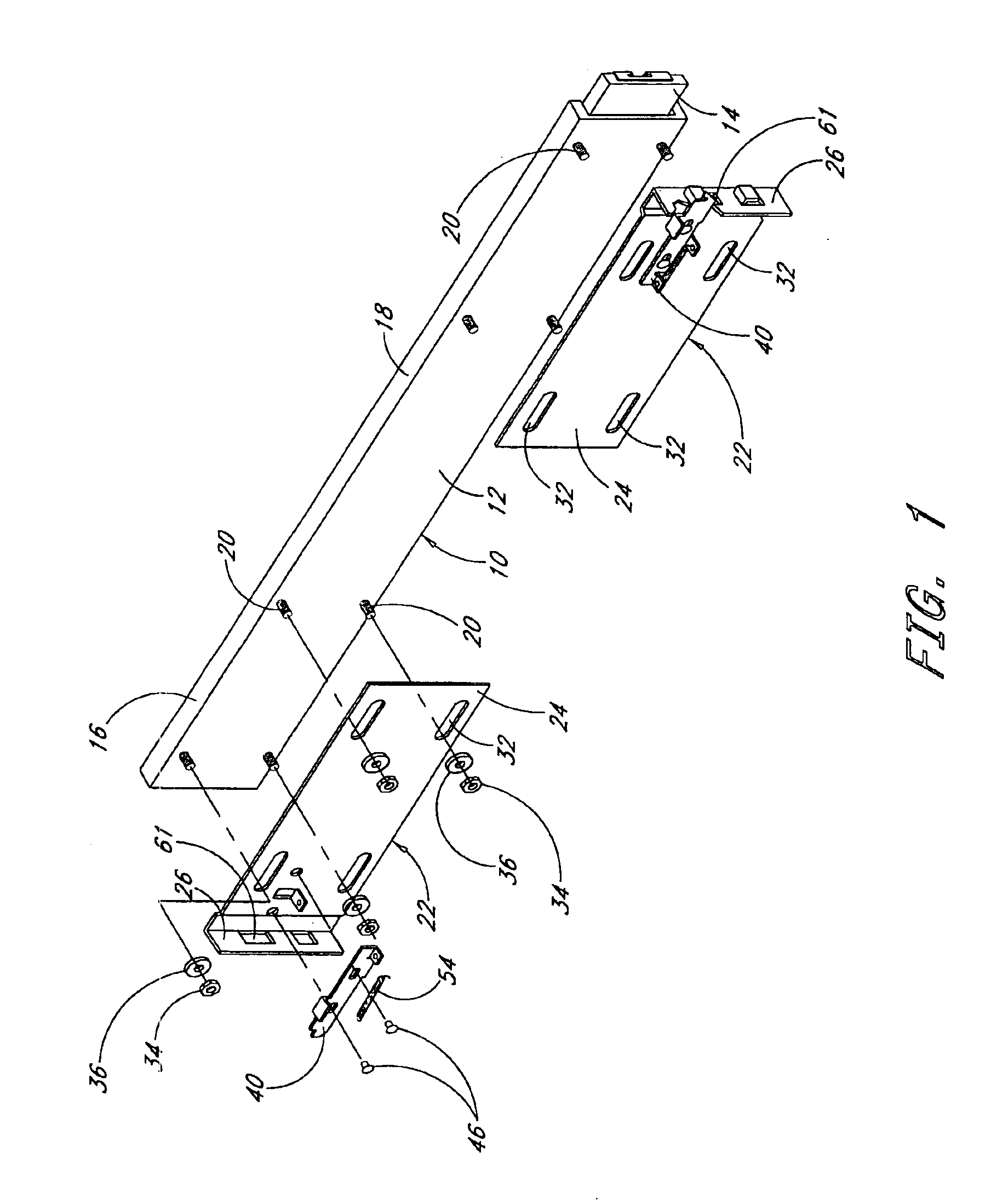
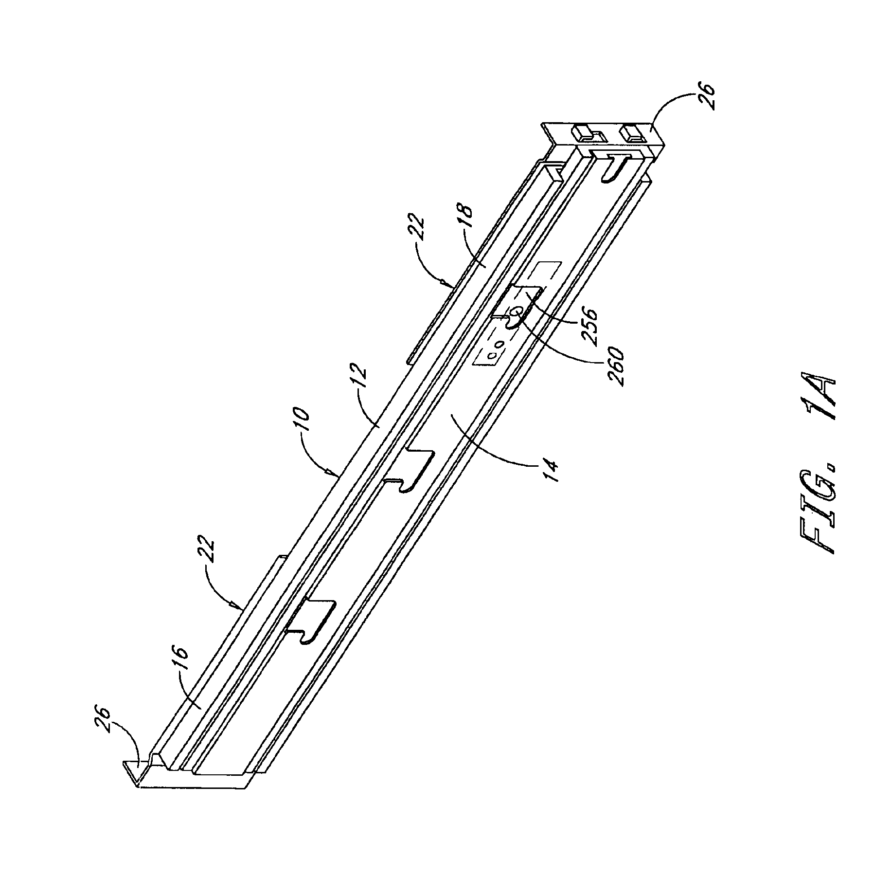
[0036]A mounting apparatus in accordance with a preferred embodiment of the present invention is illustrated in FIG. 1. In the illustrated embodiment, the apparatus includes a pair of slides 10, each having a stationary portion 12 and a telescoping portion 14. The stationary portion 12 of each slide 10 has first and second ends 16, 18 each having a plurality of threaded fasteners 20 extending therefrom.

[0037]A bracket 22 is desirably slidably mounted to each end 16, 18 of the stationary portion 12 of each slide 10. Each bracket comprises a first wall 24 which extends parallel to the slide 10 and a second wall 26 which extends generally perpendicularly from the first wall 24.

[0038]The first wall 24 of each bracket 22 has a plurality of slots 32 formed therein corresponding to the locations of the threaded fasteners 20 which extend from the stationary portion 12 of the slide 10. The brackets 22 are positioned at the ends 16, 18 of the stationary portion 12 so that the threaded fastene...


PUM


Abstract

A mounting apparatus is provided for mounting a computer server in a server rack structure. The server rack defines a first and second mounting apertures. A slide is provided having a bracket mounted to one end thereof. The bracket includes a first wall abutting the rack, and a second wall transverse to the first wall. A portion of the bracket extends into the first mounting aperture. A latch is mounted on the second wall of the bracket. The latch is movable between a first position wherein the latch extends into the second mounting aperture, and a second position wherein the latch does not extend into the mounting aperture. The latch cooperates with the portion of the bracket extending into the first mounting aperture to limit vertical movement of the bracket with respect to the rack.

Description

RELATED APPLICATION[0001]This application claims priority to U.S. Provisional Patent Application No. 60 / 190,153, filed Mar. 17, 2000, entitled COMPUTER SERVER MOUNTING APPARATUS.BACKGROUND OF THE INVENTION[0002]1. Field of the Invention[0003]The present invention relates generally to computer server mounting apparatus and, more particularly, to apparatus for slidably mounting a computer server in a server rack structure.[0004]2. Description of the Related Art[0005]For convenience and to conserve floor space, computer servers for high-capacity computer systems are often mounted in rack structures. Typically, several computer servers are mounted in each rack structure. The rack structure generally includes a rectangular frame covered by removable panels and a pivotable front access door.[0006]Each server is supported on a tray or chassis. The chassis is typically mounted on a pair of slides to allow the chassis to slide in and out of the rack structure for convenient access to the ser...

Claims


Application Information

Patent Timeline
IPC IPC(8): A47B88/04H02B1/34H02B1/00H05K7/14
CPCA47B88/044H02B1/34H05K7/1489A47B88/43
Inventor BROCK, PATTY J.NGUYEN, BAO Q.
Owner JONATHAN ENGINEERED SOLUTIONS
Learn More