Formed disk plate heat exchanger

a heat exchanger and formed disk technology, applied in the field of heat exchangers, can solve the problems of reducing fuel efficiency, gas may have an undesirable effect on the performance of the system,

Inactive Publication Date: 2005-09-27
MODINE MFG CO
View PDF16 Cites 15 Cited by
  • Summary
  • Abstract
  • Description
  • Claims
  • Application Information

AI Technical Summary

Benefits of technology

[0022]A further embodiment contemplates that the inlet and outlet extend from within the radially outer periphery of the donut-shaped heat exchanger to eliminate any obstruction to air flow by the inlet and outlet structures. In this embodiment, thermally bridged flow straightening vanes can be attached to either side of the heat exchanger.

Problems solved by technology

However, there are probably an equal number of instances where the lesser density of the gas may have an undesirable effect on the performance of the system in which the gas is being used.
These volume requirements may hinder the designer of such a system from achieving a more aerodynamic shape for the vehicle which in turn will lead to decreased fuel efficiency.

Method used


Image

  • Formed disk plate heat exchanger
  • Formed disk plate heat exchanger
  • Formed disk plate heat exchanger

Examples


Embodiment Construction

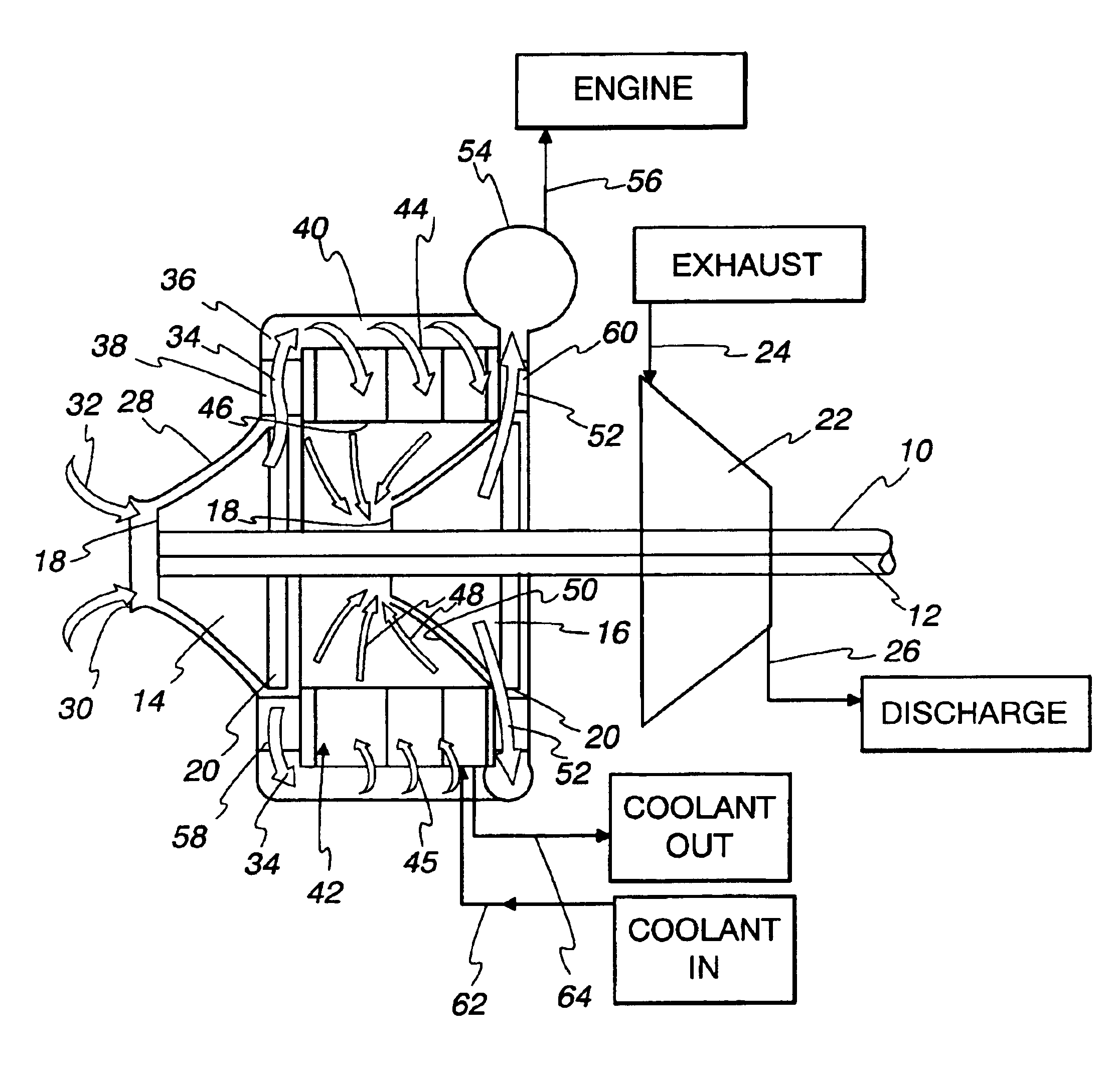
[0046]In the following description, the invention will be described in the context of a turbocharger for an internal combustion engine employed in the propulsion system of a vehicle. However, it is to be understood that the invention is not so limited. For example, it may be utilized in any compressor system wherein it is desirable to cool compressed air emanating from the compressor. It may be utilized with efficacy between stages of a multi-stage compressor, may be employed in a supercharger as well as a turbocharger, whether or not employed with a vehicle engine. Hence, no restriction to use in particular environments or with particular types of compressor systems is intended except insofar as expressly stated in the appended claims.

[0047]Referring to FIG. 1, an exemplary embodiment of the invention is illustrated and is seen to include a compressor having a rotary shaft 10 mounted by suitable means (not shown) for rotation about an axis 12. In the illustrated embodiment, two con...


PUM


Abstract

A compact rotary compressor unit within internal intercooling includes a rotary shaft (10) with at least one compressor wheel (14,16) mounted thereon for rotation therewith. The compressor wheel (14,16) has an inlet end (18) of relatively small diameter and a radial discharge end (20) of relatively large diameter. A nominally donut-shaped intercooling heat exchanger (42) is centered about the shaft (10) to receive compressed air from the compressor wheel and cool the same. Both the compressor wheel (14,16) and the heat exchanger (42) are confined in a housing (28).

Description

FIELD OF THE INVENTION[0001]This invention relates to heat exchangers, and more particularly, to a heat exchanger that is made of formed disks to define heat exchange fluid flow paths for a first fluid and which are stacked as units and sandwich fins through which a second heat exchange fluid passes.BACKGROUND OF THE INVENTION[0002]As is well known, when a gas is compressed, its temperature increases. As a consequence, the compressed gas is not as dense as it would be at the same pressure but at a lower temperature.[0003]In many instances, this is not of particular concern. However, there are probably an equal number of instances where the lesser density of the gas may have an undesirable effect on the performance of the system in which the gas is being used.[0004]A common example of the latter is in internal combustion engine systems employing superchargers or turbochargers to compress the oxidant for the fuel, typically air. When a compressed oxidant, such as air, is delivered to ...

Claims


Application Information

Patent Timeline
Patent Type & Authority Patents(United States)
IPC IPC(8): F04D25/02F02B37/00F04D25/04F02B39/00F02C7/12F02C7/141F04D29/58F28D9/00F02B29/04F02B37/013F28F13/06
CPCF02B29/0412F02B29/0462F02B29/0475F02B37/013F02B39/00F02C7/141F04D25/04F04D29/5826F28D9/0012F28F13/06Y02T10/146Y02T50/675Y02T10/144Y02T10/12Y02T50/60F04D25/024
Inventor MESHENKY, STEVEN P.BARFKNECHT, ROBERT J.CORNELL, KENNETH M.HENNES, JAMES J.GOINES, LEROYKOTTAL, PETER C.
Owner MODINE MFG CO
Why Eureka
Try Eureka