
Ultrasonic dental device

a dental device and ultrasonic technology, applied in the field of ultrasonic dental devices, can solve the problems of devices fracturing or breaking, inflammation and infection, and undesirable outcomes for the dental patient and the dental practitioner, and achieve the effect of reducing the time required and improving the distribution and placement of fluids

Inactive Publication Date: 2005-09-27
OHIO STATE INNOVATION FOUND
View PDF14 Cites 52 Cited by
  • Summary
  • Abstract
  • Description
  • Claims
  • Application Information

AI Technical Summary

Benefits of technology

[0005]The present invention further includes a means, i.e., an assembly, for delivering fluid into and through the needle while the ultrasonic generating unit is being used by the dental practitioner. This assembly includes a reservoir, such as a syringe, for storing the fluid, and a tubing assembly which includes a length of tubing and a means for connecting the tubing to the reservoir and the needle. The use of ultrasonic energy with the present invention provides the dental practitioner with numerous advantages, including improved distribution and placement of fluids, as well as a reduction in the time required for the placement of medicaments, medications, sealers, and obturating materials.

Problems solved by technology

Failure to properly debride the root canal space and to completely remove all organic matter from the same space can result in inflammation and infection.
Either outcome is undesirable for the dental patient and for the dental practitioner.
Applying ultrasonic energy to such devices, especially files, is known by those skilled in the art of dentistry to increase the effectiveness of such devices; however, certain structural features, weaknesses, or other deficiencies in the materials used to make these tools often causes the devices to fracture or break when ultrasonic energy is directed into and through them.

Method used


Image

  • Ultrasonic dental device
  • Ultrasonic dental device
  • Ultrasonic dental device

Examples


Embodiment Construction

Reference Numerals

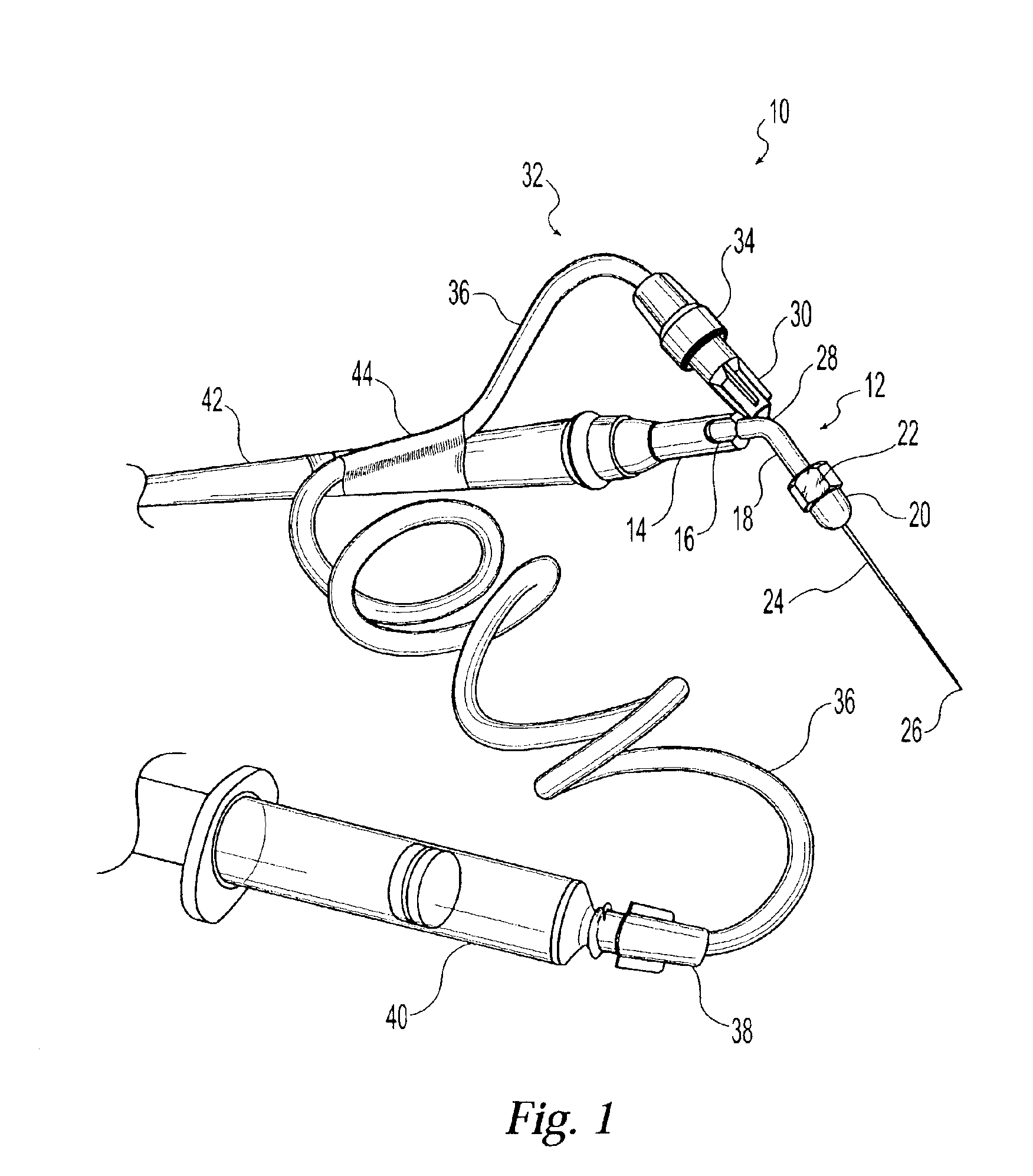
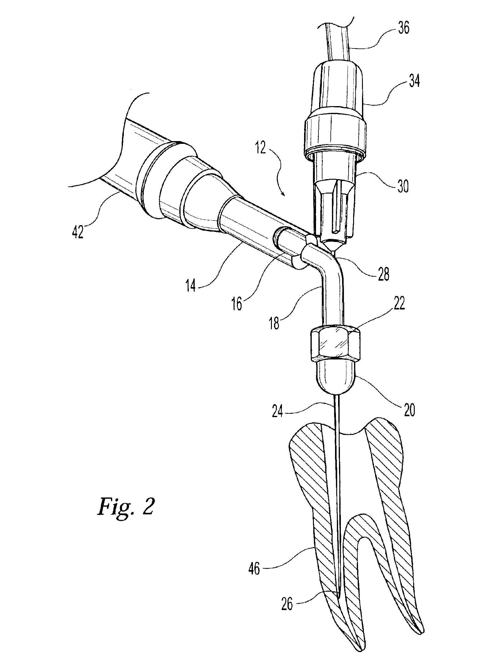
[0010]10 dental device[0011]12 shaft assembly[0012]14 threaded housing[0013]16 first planar surface[0014]18 shaft[0015]20 hub[0016]22 second planar surface[0017]24 needle[0018]26 tip[0019]28 aperture[0020]30 connector[0021]32 tubing assembly[0022]34 first collar[0023]36 length of tubing[0024]38 second collar[0025]40 syringe[0026]42 ultrasonic wand[0027]44 attachment means[0028]46 tooth

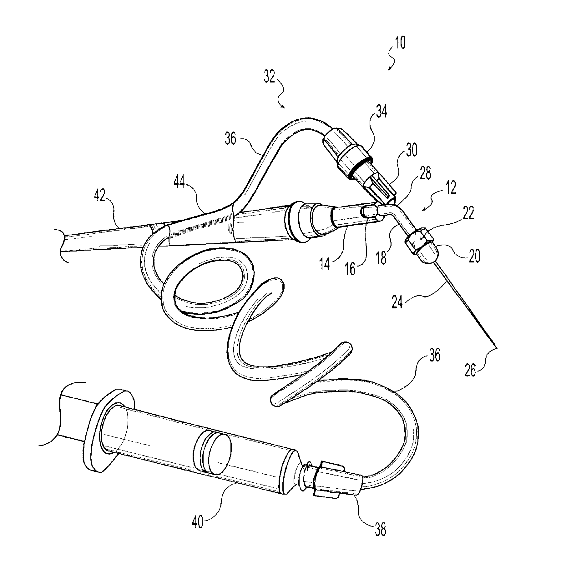
[0029]With reference to the Figures, and according to an exemplary embodiment of the present invention, dental device 10 includes a shaft assembly 12, needle 24, tubing assembly 32, syringe 40, and ultrasonic wand 42. As illustrated in FIGS. 1 and 2, shaft assembly 12 further includes a threaded housing 14, first planar surface 16, shaft 18, hub 20, and second planar surface 22. First planar surface 16 is threadably attached to ultrasonic wand 42 when dental device 10 is in operation. Threaded housing 14 further includes a first planar surface 16 on either side of the housing. This fi...


PUM


Abstract

A device for performing endodontic procedures such as root canals by utilizing ultrasonic energy to debride the root canal space. The device includes a modified shaft assembly and a stainless steel hypodermic needle which concentrates the ultrasonic energy at the tip of the needle. The shaft assembly further includes a threaded housing for attaching the shaft assembly to an ultrasonic generator, an angled shaft attached to the threaded housing, and a hub attached to the end of the angled shaft opposite the threaded housing for reducing the diameter of the bore when the hub is tightened. The angled shaft further includes a bore passing through its length and an aperture passing through the outer wall of the shaft. The aperture is positioned near the larger of the two angles formed by the angled shaft and is oriented in the direction of the hub. The needle is inserted into the aperture and passes through the bore in the angled shaft until it exits the shaft through the hub. The working length of the needle may be adjusted by the practitioner.

Description

TECHNICAL FIELD OF THE INVENTION[0001]The present invention relates generally to devices for performing dental procedures, and specifically to an ultrasonic device useful for performing certain dental procedures such as root canal therapy, i.e., endodontics.BACKGROUND OF THE INVENTION[0002]Performance of endodontic therapeutic techniques on the dental patient typically requires the proper debridement of the root canal space by the dental practitioner. As the root canal is debrided and enlarged, substrates within the tooth that may be suitable for the growth of microorganisms are reduced. Furthermore, dental practitioners have long recognized the importance of completely removing all organic matter from the root canal of the tooth prior to filling the root canal with medication or other material. Failure to properly debride the root canal space and to completely remove all organic matter from the same space can result in inflammation and infection. Such inflammation and / or infection ...

Claims


Application Information

Patent Timeline
IPC IPC(8): A61C5/02A61C1/00A61C1/07
CPCA61C1/07A61C5/02A61C5/40
Inventor NUSSTEIN, JOHN
Owner OHIO STATE INNOVATION FOUND
Learn More