

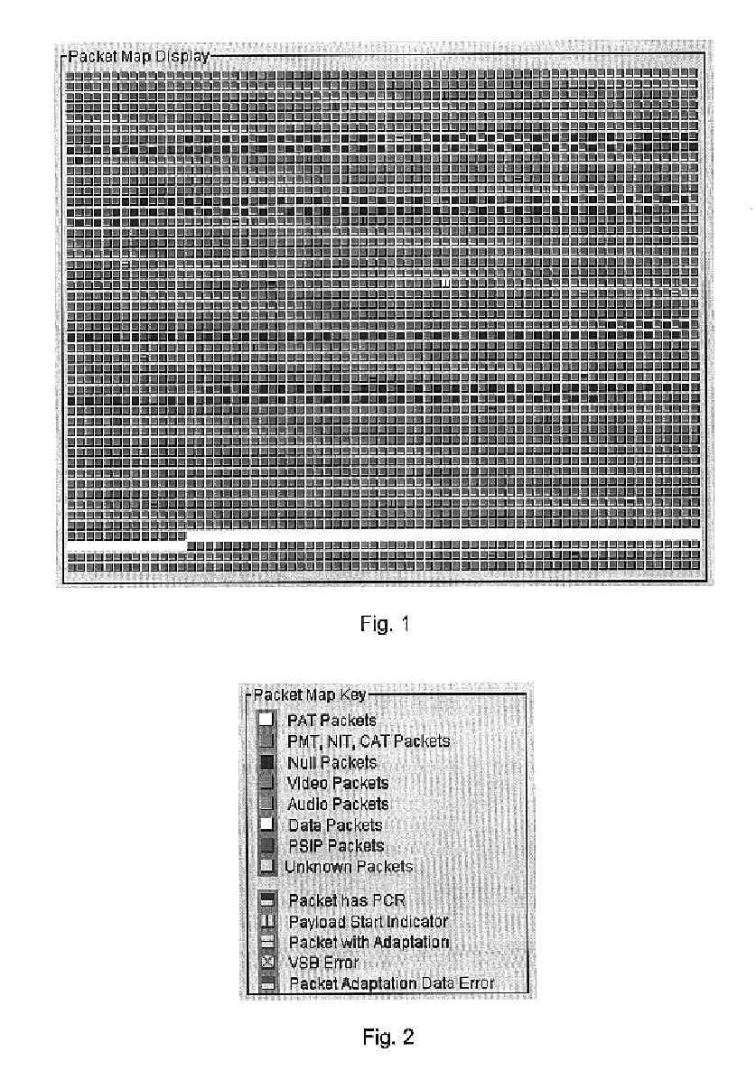
Transport stream packet map display
a packet map and transport stream technology, applied in the field of digital signal monitoring, can solve the problems of difficult analysis or visualization of high data complexity, and difficulty in understanding and visualizing such a great amount of data at even low rates, and achieve the effect of improving the visualization efficiency and analyzing the contents of such a stream
- Summary
- Abstract
- Description
- Claims
- Application Information
AI Technical Summary
Benefits of technology
Problems solved by technology
Method used
Image

Examples
Embodiment Construction
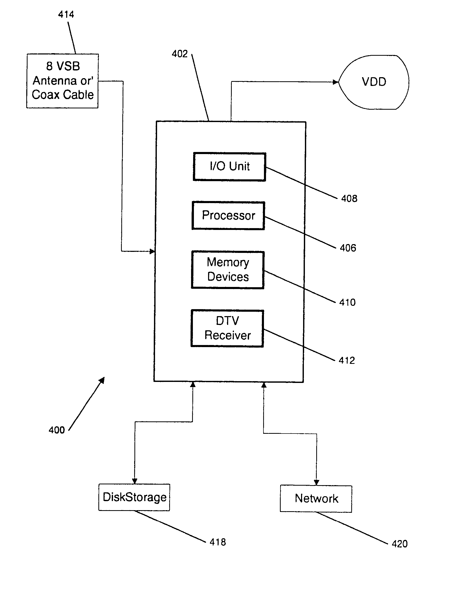
[0027]An integrated digital television (DTV) diagnostic instrument (and the method and software embodied therein) according to the invention uses known hardware programmed according to the invention. Such hardware is depicted in FIG. 4. The system 400 of FIG. 4 includes a computer / controller 402 having input / out circuitry 408, a processor 406, one or more memory devices 410 and a DTV receiver 412. The computer 402 is connected to a radio frequency (RF) antenna or to a coaxial cable via which the computer 402 receives a DTV signal, e.g., an 8 vestigial side band (VSB) signal. The output of the diagnostic instrument is provided to a video display device (VDD) 416 such as a liquid crystal display (LCD) device or cathode ray tube (CRT). Portions of DTV signals (received via the antenna / coaxial cable 414) can be saved to or retrieved from a disk storage unit 418 or from a network 420 via a connection such as an ethernet connection. The system 400 can be configured to be easily portable.
[...
PUM
 Abstract
Description
Claims
Application Information