System for thermal shaping of optical fibers

a technology of thermal shaping and optical fibers, applied in the field of optical fibers, can solve the problems of loss in connection, inability to form ideal interconnects, and loss of connectors, so as to facilitate sag control, minimize unwanted artifacts, and reduce sag

Inactive Publication Date: 2005-10-04
RDM +1
View PDF10 Cites 26 Cited by
  • Summary
  • Abstract
  • Description
  • Claims
  • Application Information

AI Technical Summary

Benefits of technology

[0015]Provided is a method that features shaping of optical fibers with various geometries, while minimizing unwanted artifacts in the optical path of the fiber core. To that end, the method facilitates control of sag in the region of an optical fiber core that is exposed to a beam of optical energy. In one example, the beam is described as consisting essentially of infra-red wavelengths, the sag is reduced, if not eliminated, by stiffening the optical fiber core to prevent the same from bending under force of gravity. In this

Problems solved by technology

Formation of the ideal interconnect is impractical for several reasons.
Connector-related losses may also arise even when there are no intrinsic variations in the fibers.
These types of losses arise when two fibers are not aligned on their center axes and lateral or axial displacement can be, and usually is, the greatest cause of loss in the connection.
Tolerances of this magnitude are difficult to achieve.
Add to this, the losses that are also induced due to angular misalignment, and the total tolerances that must be maintained in the termination process, proper fiber and/or connector end preparation becomes problematic.
These defects include hackles, burrs, and fractures.
Repeatability, however, is difficult, lowering yields and increasing the cost of the finished opt

Method used


Image

  • System for thermal shaping of optical fibers
  • System for thermal shaping of optical fibers
  • System for thermal shaping of optical fibers

Examples


Embodiment Construction

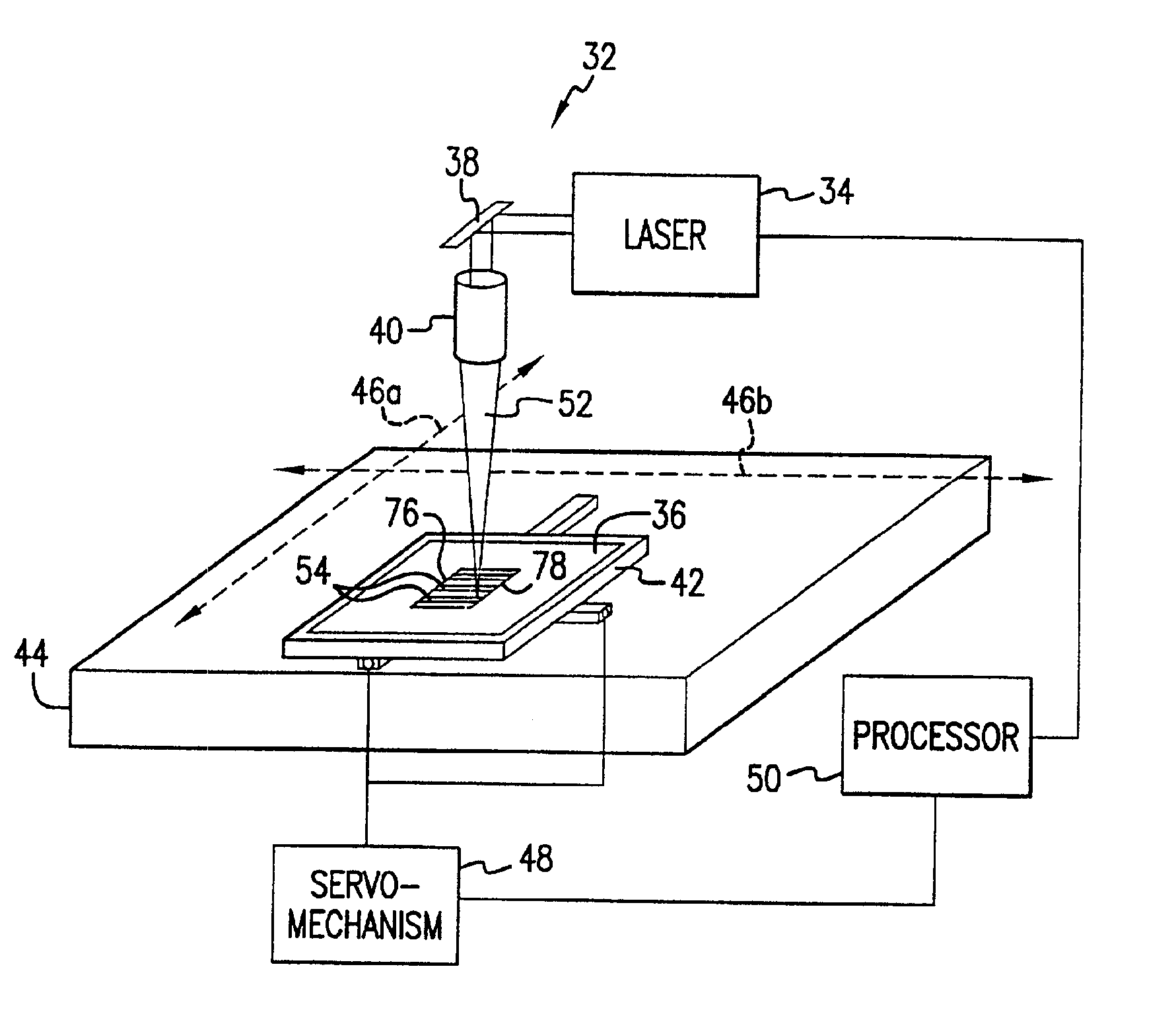
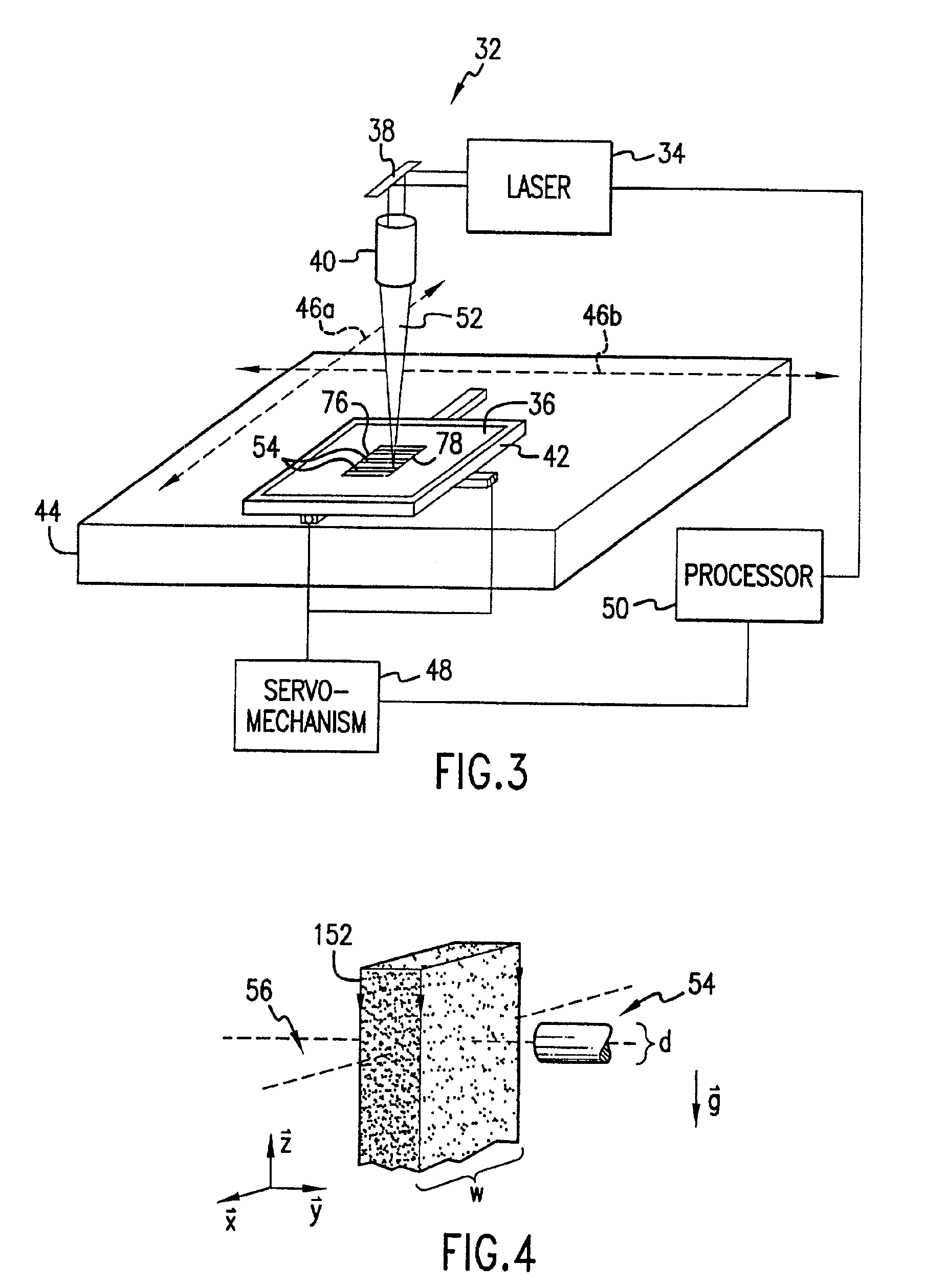
[0028]Referring to FIG. 3, an exemplary system 32 that is suitable for shaping optical fibers in accordance with the present invention. The system 32 includes a beam source 34 in optical communication with a platen 36 through a pick-off mirror 38 and beam shaping optics 40. The platen 36 is attached to a stage 42 that is moveably attached to a frame 44. Specifically, the stage 42 is moveably attached to the frame 44 to reciprocate along at least one axis 46a. The stage 42 may also be attached to move along an axis orthogonal to axis 46a, shown as 46b. To that end, a servo-mechanism 48, in data communication with a processor 50, is coupled to the stage 42 to facilitate movement along both axes 46a and 46b under control of the processor 24. In this manner, positional control along the axes 46a and 46b was achieved to within 4 μm, with the laser 34 being able to impinge a beam 52 upon any area of the platen 36, desired. In the present example, one or more optical fibers 53 are attached...


PUM

PropertyMeasurementUnit
Areaaaaaaaaaaa
Energyaaaaaaaaaa
Reflectionaaaaaaaaaa

Abstract

A system for shaping an optical fiber with various geometries while minimizing unwanted artifacts in the core of the optical fiber. The system facilitates control of sag in the region of the core that is exposed to a beam of optical energy. The sag is reduced, if not eliminated, by maintaining the cross-sectional area of the core that is exposed to the beam at thermal equilibrium.

Description

CROSS-REFERENCE TO RELATED PATENT APPLICATIONS[0001]The present patent application is a divisional patent application of U.S. patent application No. 09 / 692,991 filed on Oct. 20, 2000 now U.S. Pat. No. 6,413,450.BACKGROUND OF THE INVENTION[0002]The present invention relates to optical fibers. More particularly, the present invention is directed toward segmentation of optical fibers suitable for use with data communication.[0003]To minimize insertion loss, the loss of optical energy when coupling data links in fiber-optic communication systems, it is important to correctly match the aperture through which optical energy is transmitted with the aperture through which optical energy is detected. As a result the areas of the apertures must be correctly sized and aligned.[0004]The ideal interconnection of one fiber to another would have two fibers that are optically and physically identical and held by a connector that aligns the fibers so that the interconnection does not exhibit any inf...

Claims


Application Information

Patent Timeline
IPC IPC(8): G02B6/255G02B6/42
CPCG02B6/2552G02B6/4203
Inventor MAYS, JR., ROBERT
Owner RDM
Why Eureka
Try Eureka