Hologram screen and hologram display

a hologram and display technology, applied in the field of hologram screens and hologram displays, can solve the problems of inability to achieve satisfactory color reproducibility, inability to accurately reproduce the color of the projection apparatus, and the appearance of the projected image as greenish, so as to achieve the effect of improving image quality and being easy to repla

Inactive Publication Date: 2005-10-04
DENSO CORP
View PDF2 Cites 3 Cited by
  • Summary
  • Abstract
  • Description
  • Claims
  • Application Information

AI Technical Summary

Benefits of technology

[0062]According to an eighth aspect of the invention, it is desirable that the upward / downward light scattering device and the leftward / rightward light scattering device be both placed within 5 mm of the hologram device in the hologram screen.
[0063]If the upward / downward light scattering device, or the leftward / rightward light scattering device disposed on the image projection apparatus side of the hologram device, is spaced more than 5 mm away from the hologram device, a clear image display may not be obtained because of blurring of the image light on the hologram device.
[0064]On the other hand, if the leftward / rightward light scattering device disposed on the image observer side of the hologram device is spaced more than 5 mm away from the hologram device, the image diffracted by the hologram device is blurred by the leftward / rightward light scattering device, and in this case also, a clear image display may not be obtained.
[0065]When the upward / downward light scattering device and the leftward / rightward light scattering device are both placed within 5 mm of the hologram device, if blurring such as described above occurs, the amount of blurring can be accommodated within the image display section of the image projection apparatus, for example, within non-display portions between pixels in a liquid crystal device, the presence of pixel images projected on the screen becomes unnoticeable, and this in turn serves to improve the image quality.
[0066]According to a ninth aspect of the invention, preferably the upward / downward light scattering device and the leftward / rightward light scattering device are detachable.
[0067]The term detachable here means that “if the device once attached is removed, there is no glue or adhesive remaining on the device, and the device can be attached once again.” Making the devices detachable offers the following advantages: the hologram screen can be used properly according to the environment in which it is used, for example, in the daytime when the image brightness becomes important, the upward / downward light scattering device and the leftward / rightward light scattering device are removed, and in the nighttime when reduced image brightness does not present a problem, the upward / downward light scattering device and the leftward / rightward light scattering device are attached; and the upward / downward light scattering device and the leftward / rightward light scattering device, if damaged, can be easily replaced.

Problems solved by technology

However, the hologram screen 9 using the thus produced hologram film 92 has had the problem that the colors of the images projected by the projection apparatus 2 cannot be reproduced correctly, for example, the projected images appear somewhat greenish.
However, if the light scattering device is simply combined with the hologram film 92, satisfactory color reproducibility cannot be achieved.
The prior art hologram screen 9 has the further problems that the color changes or the viewing area becomes narrower as the observer moves away from a direct ling of sight, and that, when the screen is constructed by joining multiple holograms, color differences occur at the joins.
Furthermore, the prior art hologram screen 9 has had the problem that, as the projection distance of the image projection apparatus increases with increasing screen size, the hologram device has to be remade to match the increased projection distance and the size cannot be increased by simply combining the same components together as with television sets.

Method used


Image

  • Hologram screen and hologram display
  • Hologram screen and hologram display
  • Hologram screen and hologram display

Examples


embodiment 1

[0122]A hologram screen and a hologram display according to one embodiment of the present invention will be described with reference to FIG. 1 to FIG. 8. Of FIG. 1 to FIG. 8, FIG. 2B, FIG. 4, and FIG. 5B are top views, FIG. 7 is a perspective view, and the others are side views.

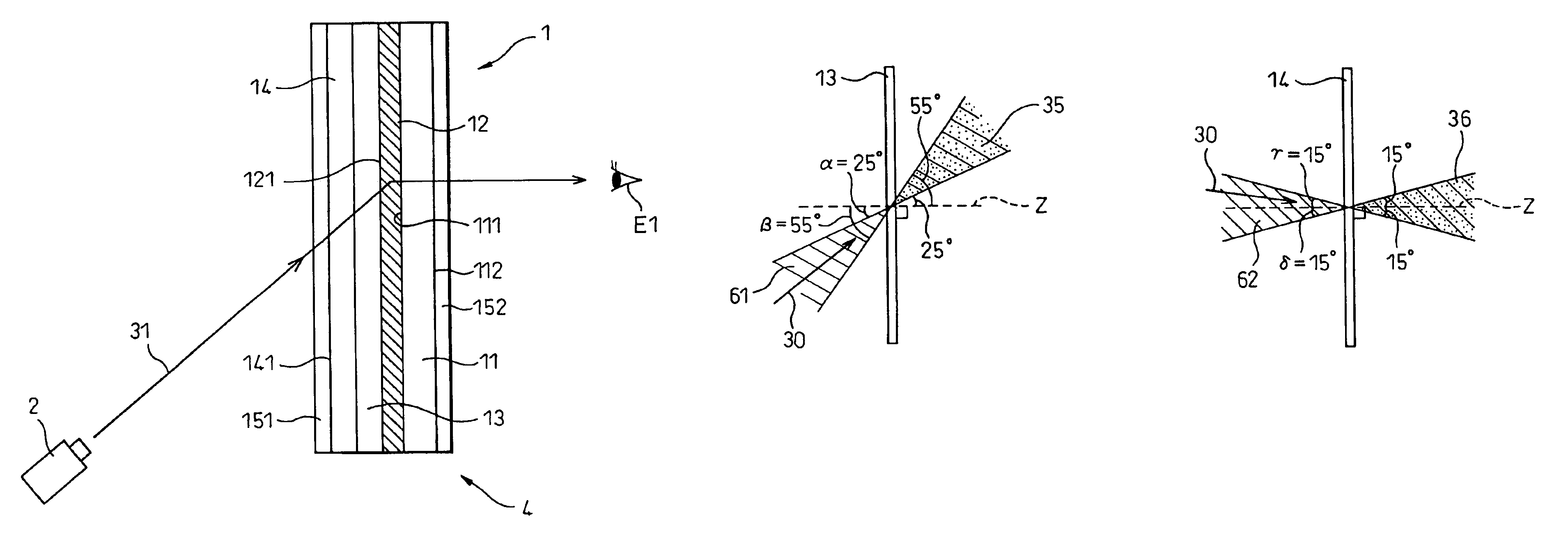
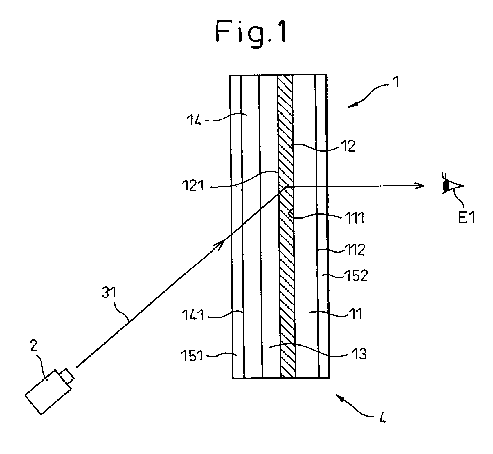
[0123]As illustrated in FIG. 1, the hologram screen 1 of this embodiment comprises a transparent member 11 and a film-like hologram device (hereinafter called the “hologram film 12”) laminated to the transparent member 11, and displays images by the image light 31 projected thereon from an image projection apparatus 2.

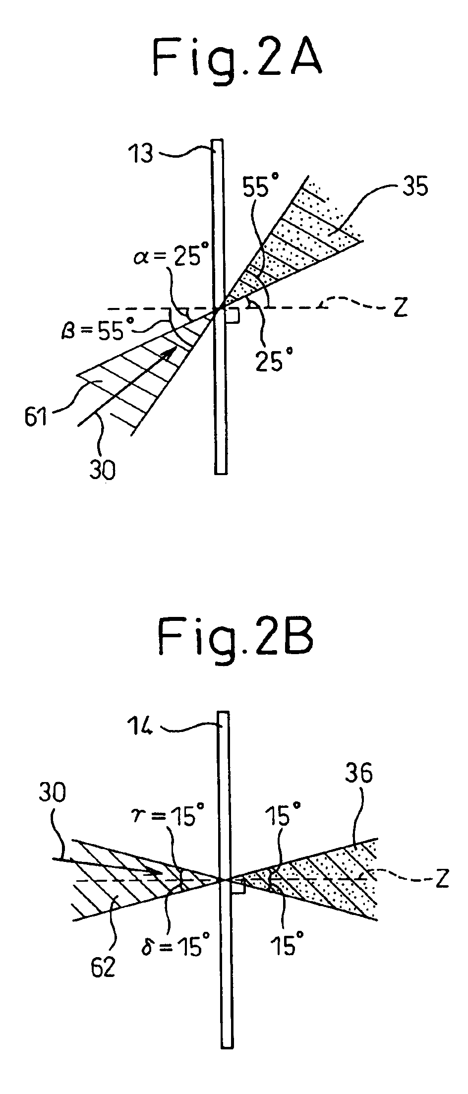
[0124]As shown in FIG. 2A and FIG. 3, a film-like light scattering device (hereinafter called the “upward / downward light scattering film 13”) for scattering incident light 30 coming from an upward / downward specific angle range 61 is placed on the image projection apparatus side 121 of the hologram film 12.

[0125]The image projection apparatus 2 projects the image light 31 toward the hologram film...

embodiment 2

[0161]As shown in FIG. 9, the hologram screen 10 of this embodiment is constructed by attaching four hologram films 12 one adjacent another onto the transparent member 11.

[0162]More specifically, the hologram films 12 consist of upper two films and lower two films joined together.

[0163]Otherwise, the construction is the same as that of the first embodiment.

[0164]In FIG. 9, the upward / downward light scattering film, leftward / rightward light scattering film, and AR films are omitted for convenience of illustration.

[0165]In the hologram screen 10 thus constructed, color differences do not arise between the hologram films 121 adjacent each other across the joints 121.

[0166]The other advantageous effects are the same as those of the first embodiment.

embodiment 3

[0167]This embodiment concerns examples of measurements of various performance factors, i.e., the chromaticity, brightness, and screen gain, made on the hologram screen 1 of the present invention as shown in FIG. 10 to FIG. 13.

[0168]First, the hologram screen of the first embodiment using both the upward / downward light scattering film and the leftward / rightward light scattering film was used as sample 1, and a hologram screen using only the upward / downward light scattering film, with the leftward / rightward light scattering film omitted, was constructed as sample 2.

[0169]Further, a prior art hologram screen using neither the upward / downward light scattering film nor the leftward / rightward light scattering film was constructed as a comparative sample.

[0170]Then, chromaticity, brightness, and screen gain were measured on each hologram screen at measurement positions a to i shown in FIG. 10.

[0171]The measured results of chromaticity are shown in FIG. 11A and FIG. 11B, and the measured r...


PUM


Abstract

A hologram screen 1 displays an image by diffracting and scattering image light 31 projected from an image projection apparatus 2. An upward/downward light scattering device 13, which scatters light incident from an upward/downward specific angle range spreading obliquely upward or downward, is placed on the image projection apparatus side of a hologram device 12 in the hologram screen 1. A leftward/rightward light scattering device 14, which scatters light incident from a leftward/rightward specific angle range spreading obliquely leftward and rightward, is placed between the hologram device 12 and the scattering device 13. The construction is such that the upward/downward specific angle range contains the incidence angle of the image light 31 on the hologram screen 1, and thus provides a hologram screen having good color reproducibility and which permits viewing of the background.

Description

BACKGROUND OF THE INVENTION[0001]1. Field of the Invention[0002]The present invention relates to a hologram screen and a hologram display for displaying images by projecting image light thereon.[0003]2. Description of the Related Art[0004]As shown in FIG. 30, it is known in the art to provide a hologram screen 9 which is attached to a store display window or the like and displays moving or still images for advertising or other purposes.[0005]The hologram screen 9 comprises, as shown in FIG. 30, a transparent member 91 and a hologram film 92 laminated to the transparent member 91.[0006]The basic concept of the hologram screen 9 is as shown in FIG. 30; that is, image light 31 is projected onto the hologram film 92 from a projection apparatus 2 (for example, a projector) positioned below (or above) the rear side of the hologram screen 9, i.e., the side opposite from the side being viewed by an image observer E, and the image light 31 focused as images on the hologram film 92 is diffrac...

Claims


Application Information

Patent Timeline
Patent Type & Authority Patents(United States)
IPC IPC(8): G02B27/01G02B5/32G03B21/10G03B21/62
CPCG02B5/32G02B27/0103
Inventor SUZUKI, KAZUNORITAKADA, KENICHIRO
Owner DENSO CORP
Why Eureka
Try Eureka