
System and method for monitoring OSNR in an optical network

a technology of optical signal tonoise ratio and optical network, which is applied in the direction of transmission monitoring, transmission monitoring/testing/fault-measurement system, electrical apparatus, etc., can solve the problems of prohibitively expensive dedicated multi-channel optical spectrum analyzer capable of simultaneously monitoring every channel in a node, and inability to achieve the desired resolution

Inactive Publication Date: 2005-10-04
CIENA
View PDF7 Cites 65 Cited by
  • Summary
  • Abstract
  • Description
  • Claims
  • Application Information

AI Technical Summary

Benefits of technology

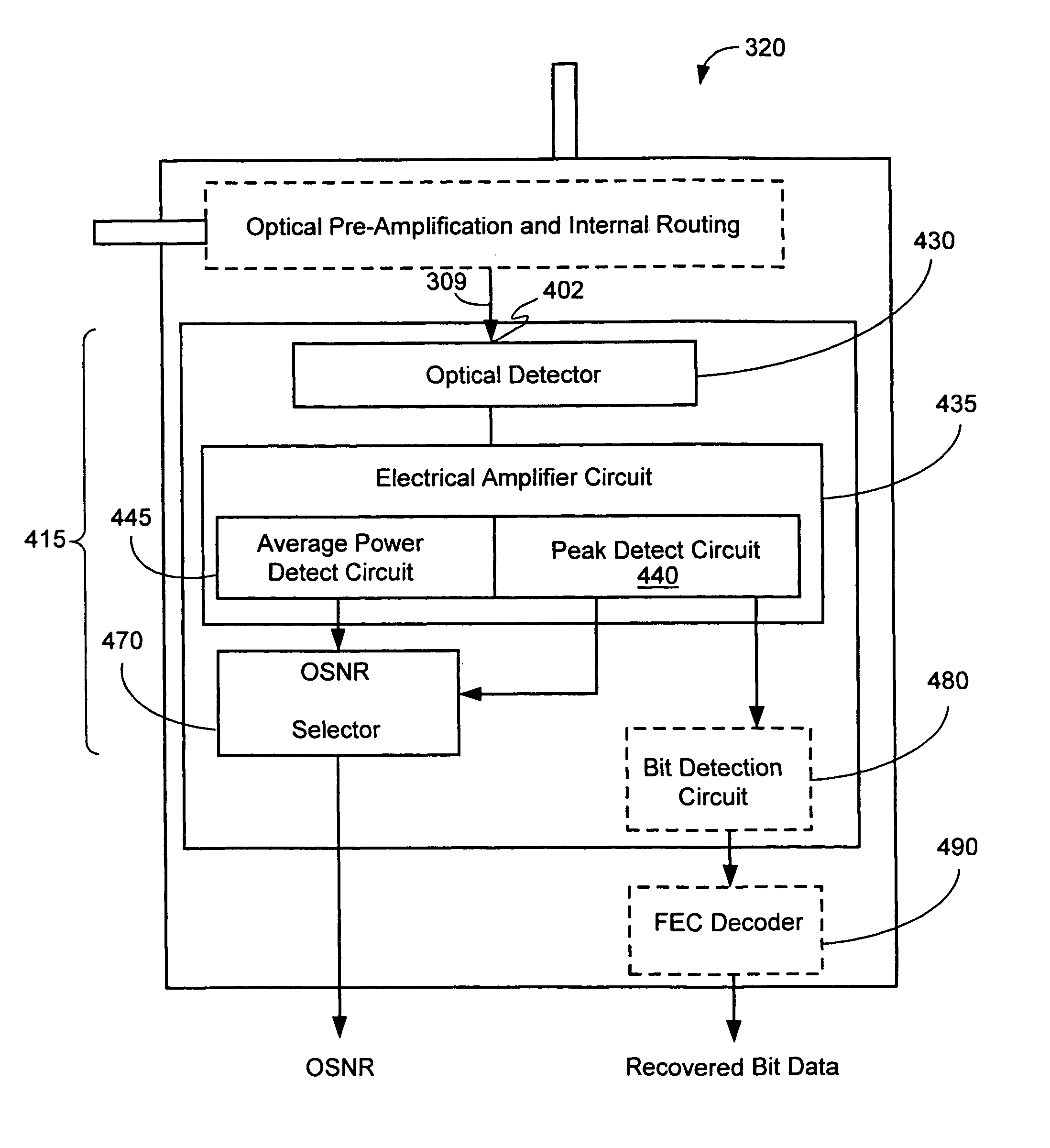
The patent describes an apparatus, system, and method for measuring the optical signal to noise ratio (OSNR) in an optical network. The system includes an optical detector, an electrical circuit for measuring the peak power level and average power level of the optical input, and an OSNR selector for selecting the OSNR based on the peak power level and average power level. The system can measure the OSNR of a wavelength channel by measuring the peak power level and average power level of an optical signal in an optical path with attenuation and optical amplifier noise. The system can be used to monitor the OSNR at selected locations and report it to other nodes, a network management system, or a link state database. The technical effect of the patent is to provide a reliable and efficient way to measure the quality of optical signals in an optical network.

Problems solved by technology

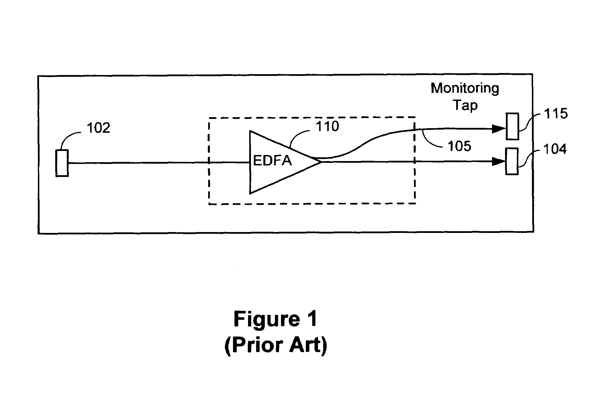
Unfortunately, conventional techniques to monitor OSNR are expensive.
A dedicated multi-channel optical spectrum analyzer capable of simultaneously monitoring every channel in a node is prohibitively expensive and has other limitations, such as speed limitations associated with using a physical grating.
However, a conventional single-channel OSNR monitor is typically expensive and may lack the desired resolution.
However, since a DWDM node may have a substantial number of channels, the total node cost of employing a conventional single-channel OSNR monitor for each channel is prohibitively large.

Method used


Image

  • System and method for monitoring OSNR in an optical network
  • System and method for monitoring OSNR in an optical network
  • System and method for monitoring OSNR in an optical network

Examples


Embodiment Construction

[0029]The present invention generally includes an apparatus, system, and method for measuring the optical signal to noise ratio (OSNR) at selected locations of an optical network, such as in selected node locations of a dense wavelength division multiplexed (DWDM) network. As described below in more detail, the capability to measure OSNR in service may be applied in the optical network to facilitate making switching, routing, or network configuration decisions to maintain the quality of service (QOS).

[0030]In an optical network, the OSNR of a particular signal depends upon the optical path that the optical signal traverses in the optical network. FIG. 3A is a block diagram illustrating an optical network 300 in which it is desired to transmit data from a first point 301 in a first node 305 to second point 309 in a second node 320 along an optical path. By way of example and not of limitation, point 301 may be a transmitter in first node 305 transmitting a signal on a wavelength chan...


PUM


Abstract

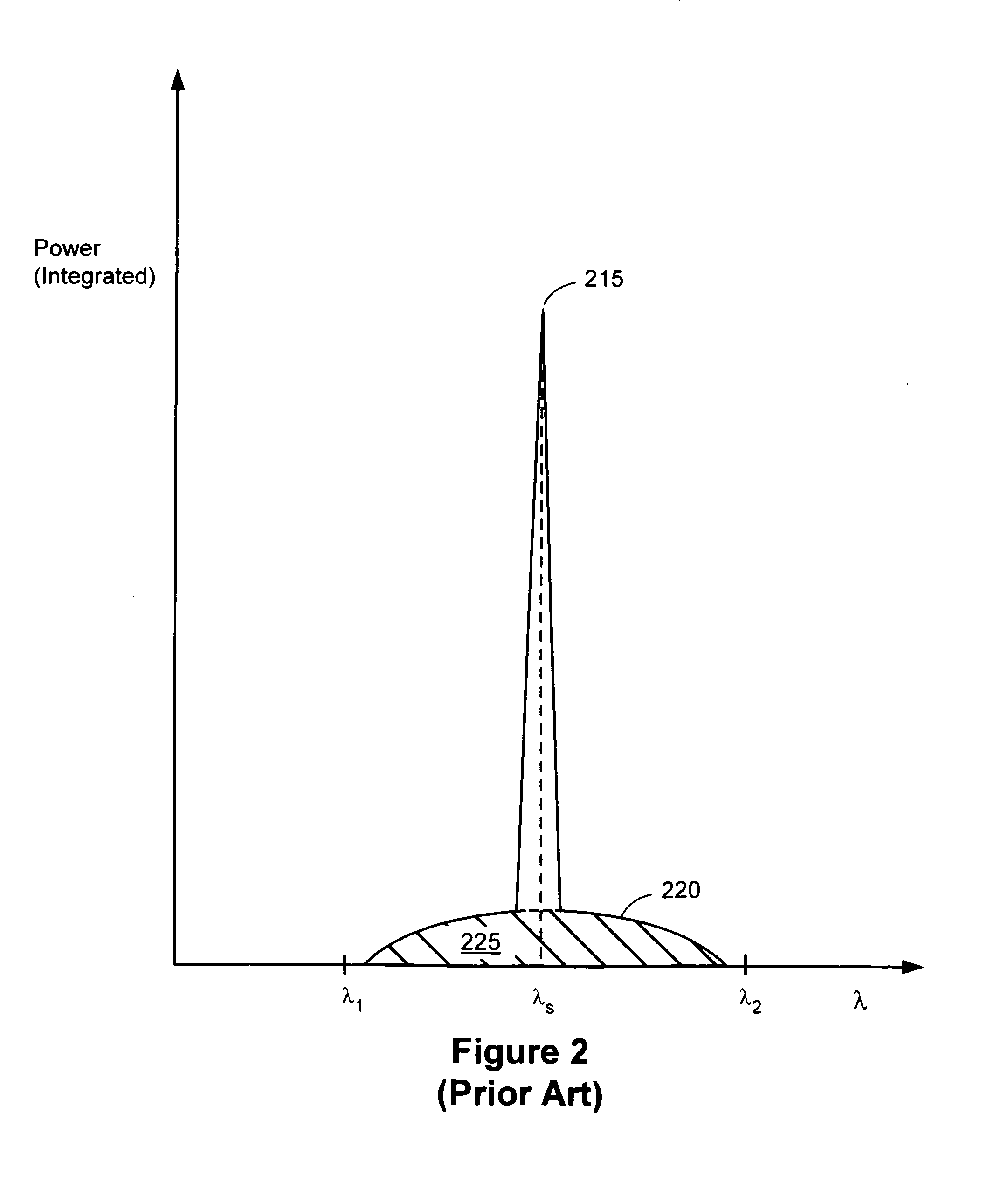
An apparatus and method for measuring optical signal to noise ratio (OSNR) in a node of an optical data network is disclosed. A peak power level and an average power level are measured for an optical input to an optical detector. The OSNR is determined by selecting an OSNR having the peak power level and the average power level associated with an optical signal traversing an optical path having attenuation and optical amplifier noise.

Description

BACKGROUND OF THE INVENTION[0001]1. Field of the Invention[0002]The present invention relates generally to measuring the optical signal-to-noise ratio (OSNR) in an optical node of an optical network. More particularly, the present invention is directed towards monitoring the OSNR in-service.[0003]2. Description of Background Art[0004]The optical signal-to-noise ratio (OSNR) is commonly used as a metric to characterize an optical path (or optical links within an optical path) of a signal of an optical network. Conventionally, an optical network is designed so that the OSNR at a receiver exceeds a selected minimum (threshold) OSNR. The threshold OSNR is commonly calculated using a power budget analysis technique. In a power budget analysis, optical signal at the receiver must have a minimum power level and a minimum OSNR to achieve a desired bit error rate (BER). The threshold OSNR typically depends upon the bit rate and the transmitter-receiver technology. For example, a forward erro...

Claims


Application Information

Patent Timeline
Patent Type & Authority Patents(United States)
IPC IPC(8): H04B17/00H04B10/08H04B10/02
CPCH04B10/07953
Inventor MITTAL, ROHIT
Owner CIENA
Learn More