Ink-jet head having passage unit and actuator units attached to the passage unit, and ink-jet printer having the ink-jet head

a technology of actuator units and actuator units, which is applied in the direction of printing, inking apparatus, etc., can solve the problems of reducing the manufacturing yield of the printer head, affecting the printing quality of the ink cartridge, so as to achieve accurate positioning relative to each other, suppress the increase of the positional shift between the electrode and the pressure chamber of the actuator unit, and improve the printing quality

Inactive Publication Date: 2005-10-11
BROTHER KOGYO KK
View PDF13 Cites 8 Cited by
  • Summary
  • Abstract
  • Description
  • Claims
  • Application Information

AI Technical Summary

Benefits of technology

[0018]In this construction, each of the actuator units can be positioned to the passage unit independently of each other. Therefore, even in case of a long head, the increase in positional shift between electrode and pres...

Problems solved by technology

Thus, the longer the head is, the more difficult the positioning process is between the pressure chambers in the passage unit and the individual electrodes in the actuator unit.
As a result, the manufacturing yield for the printer heads is reduced.
Furthermore, because the actuator unit it is...

Method used


Image

  • Ink-jet head having passage unit and actuator units attached to the passage unit, and ink-jet printer having the ink-jet head
  • Ink-jet head having passage unit and actuator units attached to the passage unit, and ink-jet printer having the ink-jet head
  • Ink-jet head having passage unit and actuator units attached to the passage unit, and ink-jet printer having the ink-jet head

Examples


first embodiment

[0119]FIG. 11 shows is a plan view of a head main body of an ink-jet head according to second exemplary embodiment of the invention. In the ink-jet head and ink-jet printer according to this second exemplary embodiment, because the parts other than the head main body are similar to those of the above-described first embodiment, the detailed description thereof will be omitted.

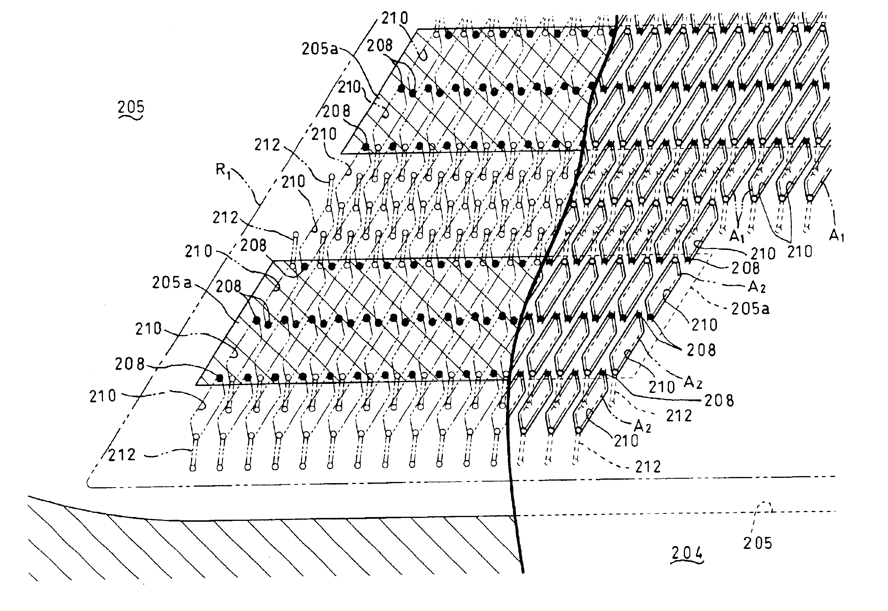
[0120]Referring to FIG. 11, a head main body 201 of an ink-jet head according to this embodiment has a rectangular shape in a plan view extending in a main scanning direction. The head main body 201 includes a passage unit 204 in which a large number of pressure chambers 210 and a large number of ink ejection ports 208 are formed, as will be described later. Onto the upper face of the passage unit 204, two parallelogrammic actuator units 221 (In FIG. 11, the right and left ones are denoted by reference numerals 221a and 221b, respectively) are bonded so as to neighbor each other. Each actuator unit 221 is dispo...

third embodiment

[0174]FIG. 29A is a plan view of a head main body in which each actuator unit is made into a heptagonal shape. FIG. 29B is a plan view of an actuator unit included in the head main body of FIG. 29A. As apparent from FIGS. 29A and 29B, in this modification, the components of the head main body 361 other than the actuator units 362 (In FIGS. 29A, they are denoted by reference numerals 362a, 362b, 362c, and 362d, respectively, in order from the right) are constructed like those of the head main body 301 of the

[0175]Referring to FIG. 29B, each actuator unit 362 has its profile in which one corner of a hexagon according to the above-described embodiment has been cut off along a straight line. As a result, the number of straight portion L is seven (L8 to L14), and as for the angle of each corner, θ8 to θ12 are about 120° and θ13 and θ14 are about 150°.

[0176]FIG. 30A is a plan view of a head main body in which each actuator unit is made into an octagonal shape. FIG. 30B is a plan view of a...


PUM


Abstract

An ink-jet head having a passage unit including pressure chambers each having one end coupled to a nozzle and the other end to be coupled to an ink supply source. The pressure chambers are arranged along a plane to neighbor each other. The ink-jet head further includes actuator units attached to a surface of the passage unit for changing the volume of each pressure chamber. Each actuator unit includes pressure generation portions respectively corresponding to pressure chambers, and is formed to extend over the pressure chambers. The actuator units are arranged along the longitudinal direction of the passage unit so that each neighboring actuator units partially overlap each other in the lateral direction of the passage unit. Each actuator unit has a basic region where many pressure generation portions are formed in a matrix, and an additional region neighboring the basic region in the lateral direction of the passage unit. In the additional region, pressure generation portions are formed to correspond to a gap portion between the pressure generation portions in the basic region of the actuator unit and the pressure generation portions in the basic region of another actuator unit neighboring that actuator unit.

Description

CROSS-REFERENCE TO RELATED APPLICATION[0001]This application is a continuation-in-part of an earlier U.S. application having U.S. Ser. No. 10 / 305,979, filed on Nov. 29, 2002, which is incorporated herein by reference in its entirety.BACKGROUND OF THE INVENTION[0002]1. Field of Invention[0003]The invention relates to an ink-jet head for printing by ejecting ink onto a print medium, and to an ink-jet printer having the ink-jet head.[0004]2. Description of Related Art[0005]In an ink-jet printer, an ink-jet head distributes ink supplied from an ink tank to pressure chambers. The ink-jet head selectively applies pressure to each pressure chamber to eject ink through a nozzle. As a means for selectively applying pressure to the pressure chambers, an actuator unit may be used in which ceramic piezoelectric sheets are laminated.[0006]As an example, a generally known ink-jet head has one actuator unit in which continuous flat piezoelectric sheets extending over a plurality of pressure chambe...

Claims


Application Information

Patent Timeline
IPC IPC(8): B41J2/14B41J2/145B41J2/155B41J2/045B41J2/16
CPCB41J2/14209B41J2/14233B41J2/145B41J2/155B41J2002/14217B41J2002/14225B41J2202/20B41J2002/14306B41J2002/14419B41J2002/14459B41J2202/11B41J2202/19B41J2002/14258B41J2/1433
Inventor SAKAIDA, ATSUOASANO, TAKESHIHIROTA, ATSUSHI
Owner BROTHER KOGYO KK
Why Eureka
Try Eureka