Ink-jet printing apparatus and ink-jet printing method

Inactive Publication Date: 2005-10-11
CANON KK
View PDF9 Cites 22 Cited by
  • Summary
  • Abstract
  • Description
  • Claims
  • Application Information

AI Technical Summary

Benefits of technology

[0010]An object of the present invention is to provide an ink-jet printing apparatus and an ink-jet printing method which can improve a quick-drying performance of an ink containing an ultraviolet curing agent while at the same time preventing harm done by ink mist.
[0021]In this invention, when the printing head ejects ink containing an ultraviolet curing agent from the ink ejection portions as it moves, an ultraviolet light is emitted onto the ink adhering to the printing medium from a position in front of the ink ejection portions with respect to the printing head moving direction. This prevents the ink mist flowing rearward with respect to the head moving direction from being radiated with the ultraviolet light. As a result, it is possible to prevent a degradation of image quality that would be caused by the ink mist hardened through the radiation of the ultraviolet light being scattered over the printing medium and therefore harm caused by the ink mist.
[0022]Further, with this invention, the ink containing an ultraviolet curing agent is ejected while moving in one of the main scan directions and, after that, when the printing head moves in the other of the main scan directions, an ultraviolet light is shed on the ink adhering to the printing medium. Therefore, the printing head is moving in one of the main scan directions and shining an ultraviolet light when the printing head is moving in the other of the main scan directions. Accordingly, application of the ultraviolet light to the ink mist is avoided, thereby preventing harm done by the ink mist.
[0023]Further, this invention provides a shutter that shields the ultraviolet radiation unit when the unit does not shine the ultraviolet light. This reliably prevents a harm done by the ink mist when it adheres to the ultraviolet radiation unit.

Problems solved by technology

The serial printer of such a construction has a problem that when the surface of a printing medium is rubbed immediately after an image has been printed, the printed image may be spoiled or the surface of the printing medium may be smeared.
Further, when a plurality of color inks are used for printing, different color inks may flow over a boundary into each other's area (bleeding), degrading an image quality.
These conventional apparatus, however, do not consider a problem of ink mist produced during printing, i.e., the adverse effects that fine ink droplets (other than the intended main ink droplets) floating over the printing medium have on the print quality.
As a result, the solidified fine ink particles are scattered over the printed surface of the printing medium, degrading the quality of the printed image.
In that case, the ultraviolet light emitted from the ultraviolet radiation unit may weaken in intensity.
Further, when an ultraviolet lamp with its length corresponding to the width of the printing medium is used, as in the second example of the first prior art, the cost increases.
In addition, because it takes time for the printed ink to become fixed, when a plurality of color inks are used for printing in particular, the ink bleeding at a boundary between different color ink areas adversely affects the image.

Method used


Image

  • Ink-jet printing apparatus and ink-jet printing method
  • Ink-jet printing apparatus and ink-jet printing method
  • Ink-jet printing apparatus and ink-jet printing method

Examples


first embodiment

(First Embodiment)

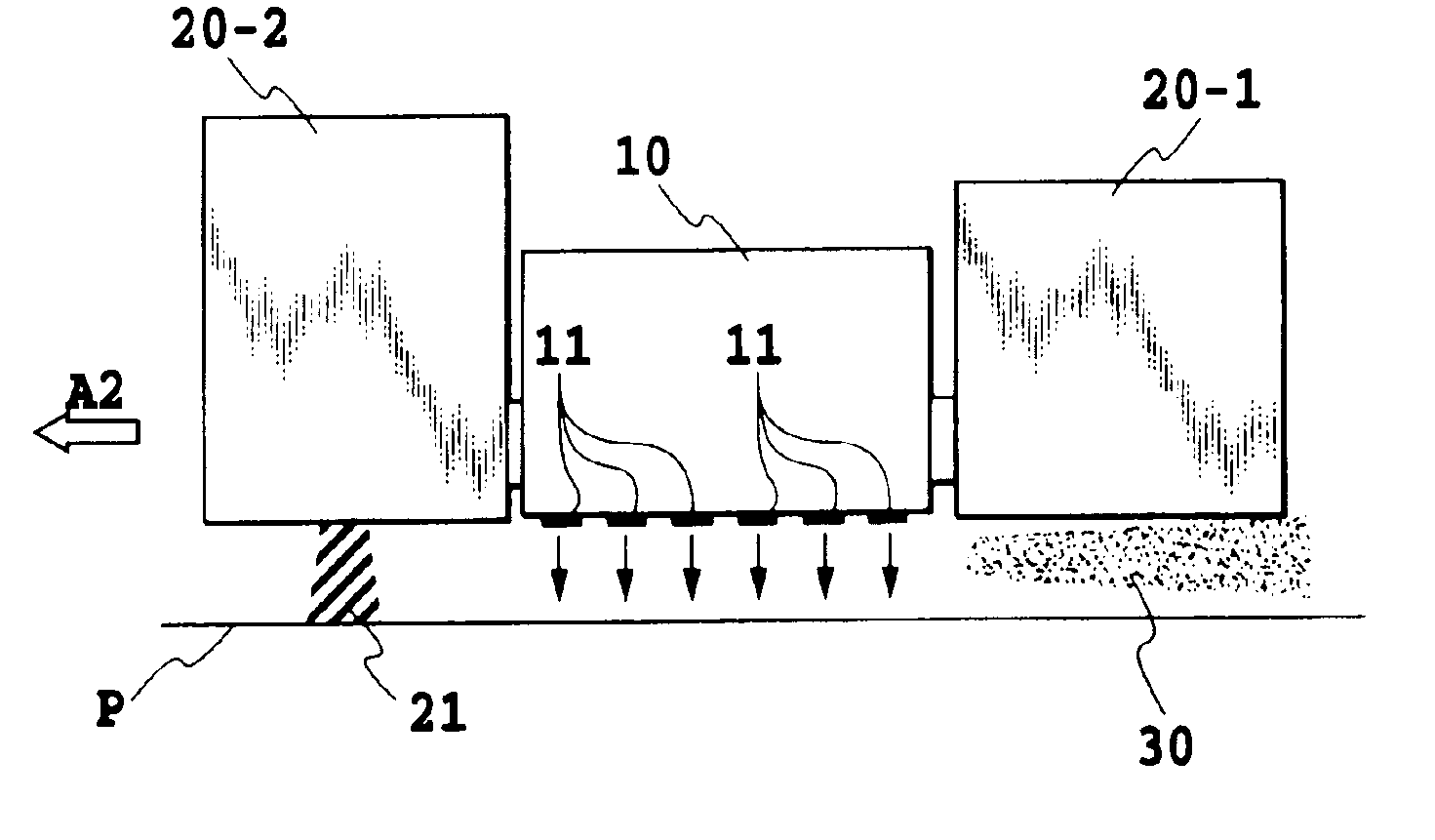
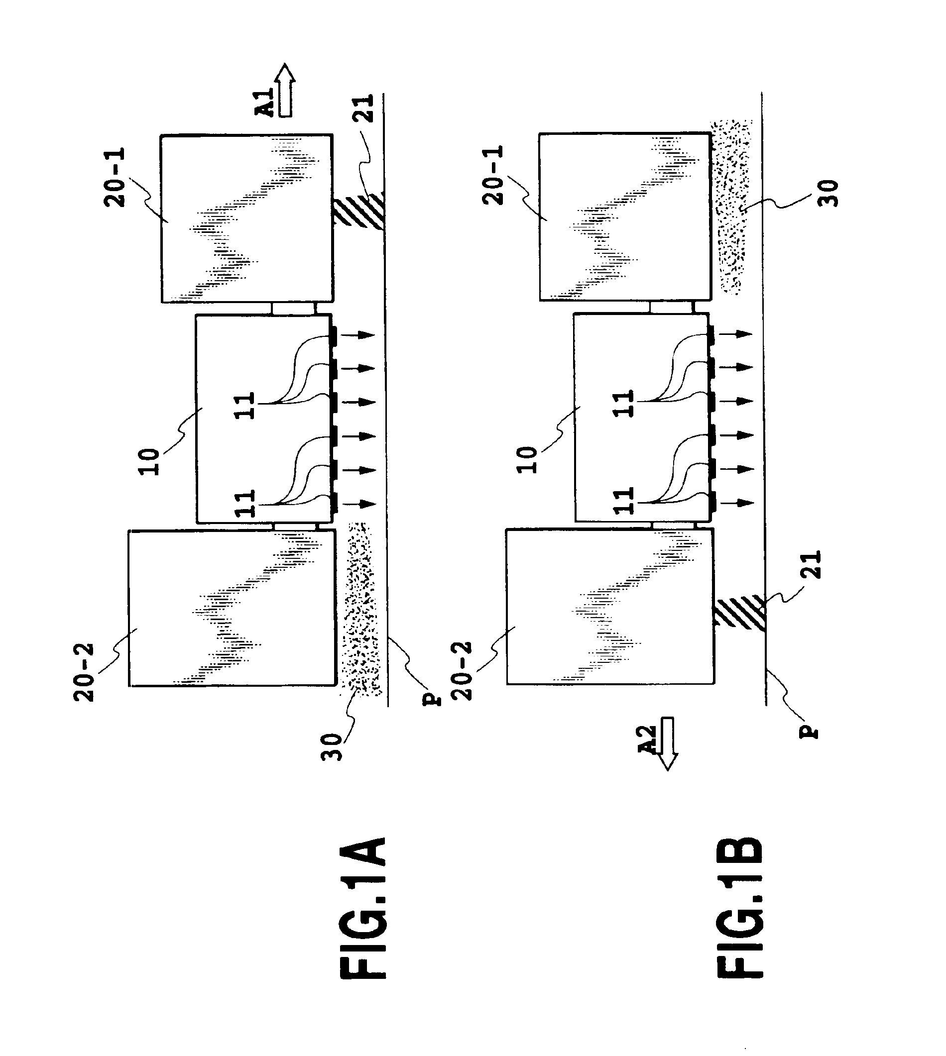
[0058]FIG. 1A and FIG. 1B best illustrate the features of the first embodiment of the present invention.

[0059]In this example, ultraviolet radiation units 20 (20-1, 20-2) are provided at both ends of the printing head 10 in the ink-jet printing apparatus of FIG. 11. As shown in FIG. 1A, when the printing head 10 is moving toward the right in the direction of arrow A1, ink ejection portions 11 of the printing head 10 eject ink and at the same time the right-side ultraviolet radiation unit 20-1 radiates an ultraviolet light 21. When, as shown in FIG. 1B, the printing head 10 is moving toward the left in the direction of arrow A2, the ink ejection portions 11 of the printing head 10 eject ink and at the same time the left-side ultraviolet radiation unit 20-2 radiates the ultraviolet light 21. Therefore, the ultraviolet light 21 is radiated from the ultraviolet radiation unit 20 situated on the front side of the printing head 10 with respect to the scan direction. The ...

second embodiment

(Second Embodiment)

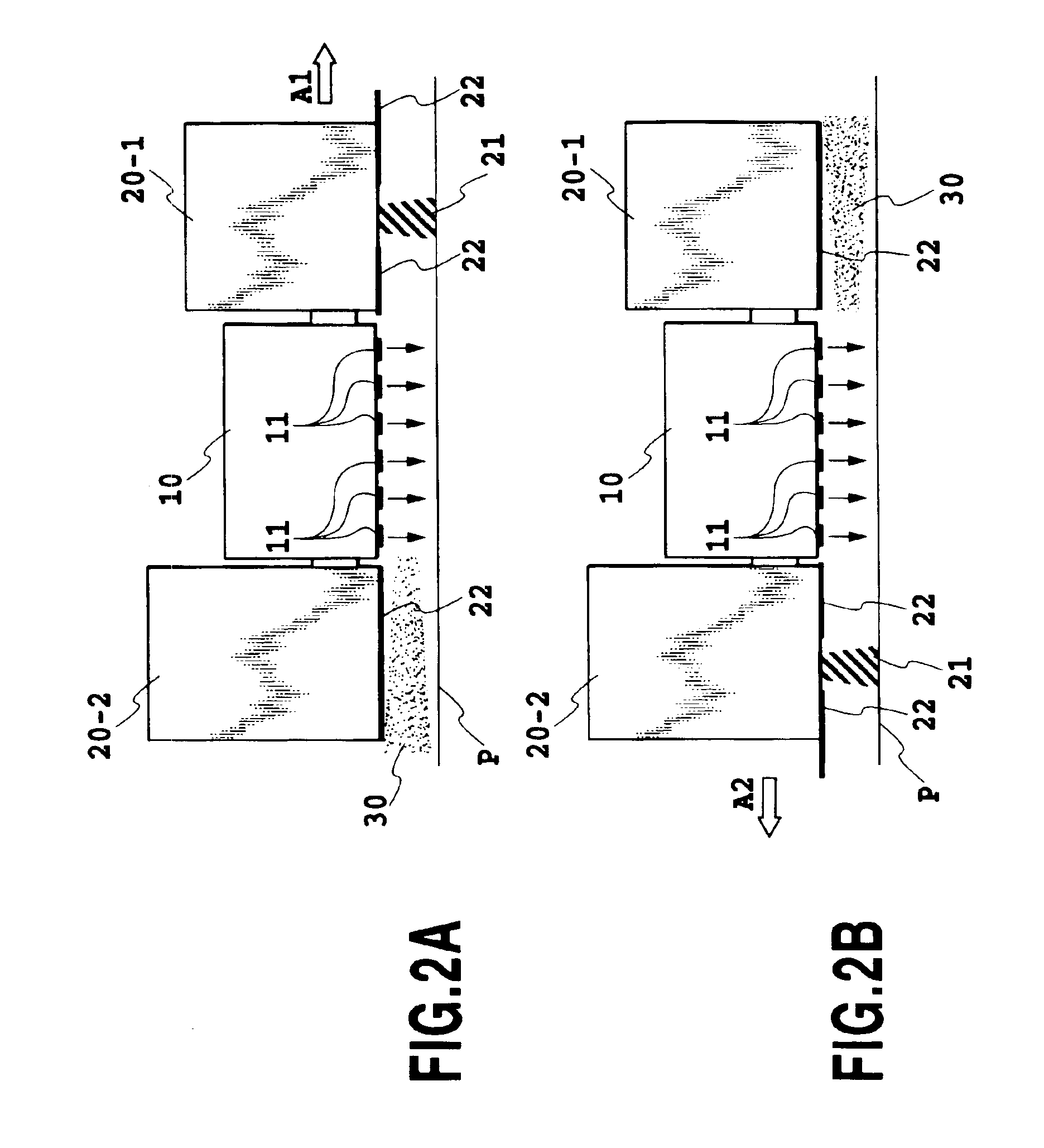
[0061]FIG. 2A and FIG. 2B best illustrate the features of the second embodiment of the present invention.

[0062]The apparatus of this embodiment has shutters 22 attached to the ultraviolet radiation units 20 (20-1, 20-2) of the first embodiment. The shutter 22 on the right side ultraviolet radiation unit 20-1 opens to form a passage for the ultraviolet light 21 when the ultraviolet radiation unit 20-1 radiates the ultraviolet light 21, i.e. when the printing head 10 moves to the right in the direction of arrow A1 as shown in FIG. 2A. The shutter 22 on the left side ultraviolet radiation unit 20-2 opens to form an ultraviolet light passage when the ultraviolet radiation unit 20-2 radiates the ultraviolet light 21, i.e. when the printing head 10 moves to the left in the direction of arrow A2 as shown in FIG. 2B. The shutters 22 are closed to shield the corresponding ultraviolet radiation units 20-1, 20-2 when they do not radiate the ultraviolet light 21.

[0063]The mis...

third embodiment

(Third Embodiment)

[0064]FIG. 3A and FIG. 3B best illustrate the feature of the third embodiment of the present invention.

[0065]This embodiment has an ultraviolet radiation unit 20 provided at one end of the printing head 10 in the ink-jet printing apparatus. As shown in FIG. 3A, when the printing head 10 is moving in the direction of arrow A1, the ink ejection portions 11 of the head 10 eject ink and at the same time the ultraviolet radiation unit 20 radiates the ultraviolet light 21. When, as shown in FIG. 3B, the head 10 is moving in the direction of arrow A2, the ink ejection portions 11 of the head 10 do not eject ink, nor does the ultraviolet radiation unit 20 radiate the ultraviolet light. Radiating the ultraviolet light 21 from the ultraviolet radiation unit 20 situated in front of the head 10 with respect to the scan direction of arrow A1 in this way fixes the ink on a printed area of the paper P that was printed in the previous scan. Thus, when an image in a predetermined a...


PUM


Abstract

An ink-jet printing apparatus and an ink-jet printing method are provided which can improve a quick-drying performance of an ink containing an ultraviolet curing agent while at the same time preventing harm done by ink mist. When the printing head ejects ink containing the ultraviolet curing agent from the ink ejection portions as it moves, the ultraviolet radiation unit provided in front of the printing head with respect to the printing head moving direction radiates the ultraviolet light onto the ink adhering to the printing medium.

Description

[0001]This application is based on Patent Application No. 2001-199987 filed Jun. 29, 2001 in Japan, the content of which is incorporated hereinto by reference.BACKGROUND OF THE INVENTION[0002]1. Field of the Invention[0003]The present invention relates to an ink-jet printing apparatus and an ink-jet printing method for printing on a printing medium by using a printing head capable of ejecting ink.[0004]2. Description of the Related Art[0005]The ink-jet system performs printing by projecting ink droplets (printing liquid droplets) from nozzles of the printing head onto the printing medium.[0006]The serial printer of such a construction has a problem that when the surface of a printing medium is rubbed immediately after an image has been printed, the printed image may be spoiled or the surface of the printing medium may be smeared. Further, when a plurality of color inks are used for printing, different color inks may flow over a boundary into each other's area (bleeding), degrading a...

Claims


Application Information

Patent Timeline
IPC IPC(8): B41J11/00B41J2/01
CPCB41J11/002B41J11/00214B41J11/00218
Inventor SHIRAKAWA, HIROAKI
Owner CANON KK
Why Eureka
Try Eureka