Imager cover-glass mounting

a technology for imaging devices and covers, which is applied in the field of protective covers for imaging devices, can solve the problems of reducing the image quality produced by the imaging device, affecting the operation of the imaging device, and affecting the image quality of the imaging devi

Inactive Publication Date: 2005-10-11
GE INSPECTION TECH LP
View PDF24 Cites 50 Cited by
  • Summary
  • Abstract
  • Description
  • Claims
  • Application Information

AI Technical Summary

Benefits of technology

[0013]In yet another aspect of the invention, an imaging device is provided with an imager window cover element which protects optical elements of the imaging device from adverse environmental conditions.

Problems solved by technology

This method of protecting the imager window, however, creates certain disadvantages with regard to the operation of the imaging device.
In practice, the presence of these rings (which typically are a series of concentric rings surrounding a central dark spot) reduces the image quality produced by the imaging device.
Furthermore, the UV adhesives used to bond the flat optical element to the imager window, when stressed mechanically or thermally, tend to fail and crack, creating unwanted distortions and artifacts in the image produced by the imaging device.
The failure of these adhesives also allows the flat optical element to disengage from the imager window, losing any protective benefit conferred by the presence of the flat optical element.
That approach, however, is disadvantageous in that it requires additional materials and time-consuming alignment and bonding steps with regard to the bonding pads.
However, this approach also is flawed in that the preformed adhesive strips cannot be tightly controlled when melted under heat, allowing the adhesive to “run” into the viewing area of the imager window.

Method used


Image

  • Imager cover-glass mounting
  • Imager cover-glass mounting
  • Imager cover-glass mounting

Examples


Embodiment Construction

[0018]It is to be understood that the invention is not limited in its application to the details of construction and arrangements of components set forth herein in the detailed description of the preferred embodiment or illustrated in the drawings. The invention is capable of other embodiments and of being practiced or being carried out in various ways.

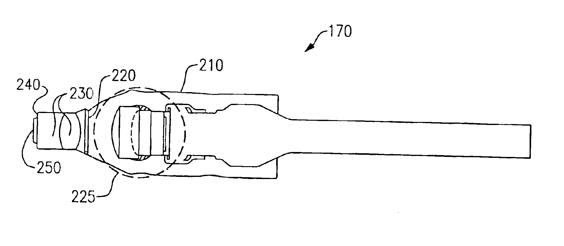
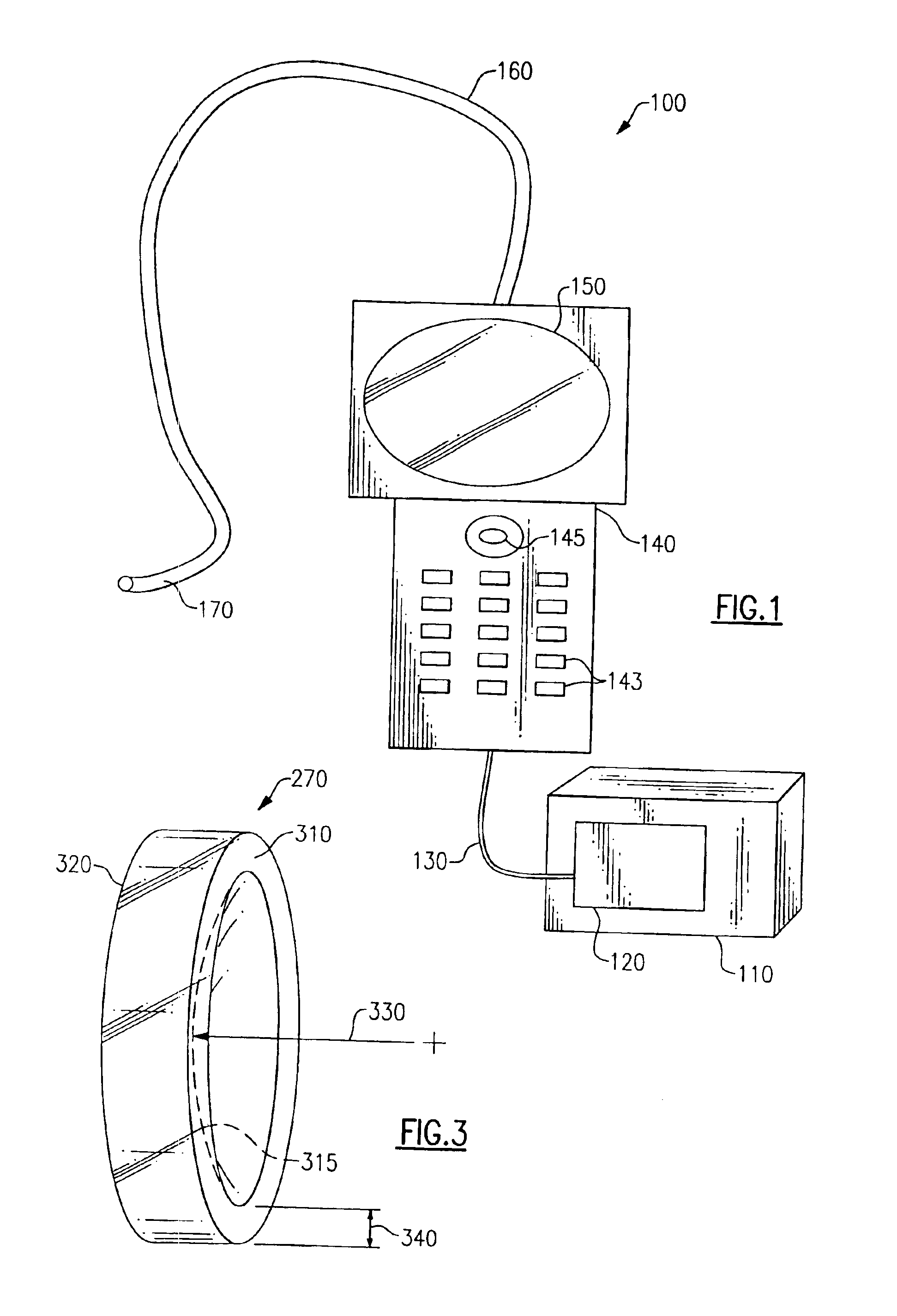
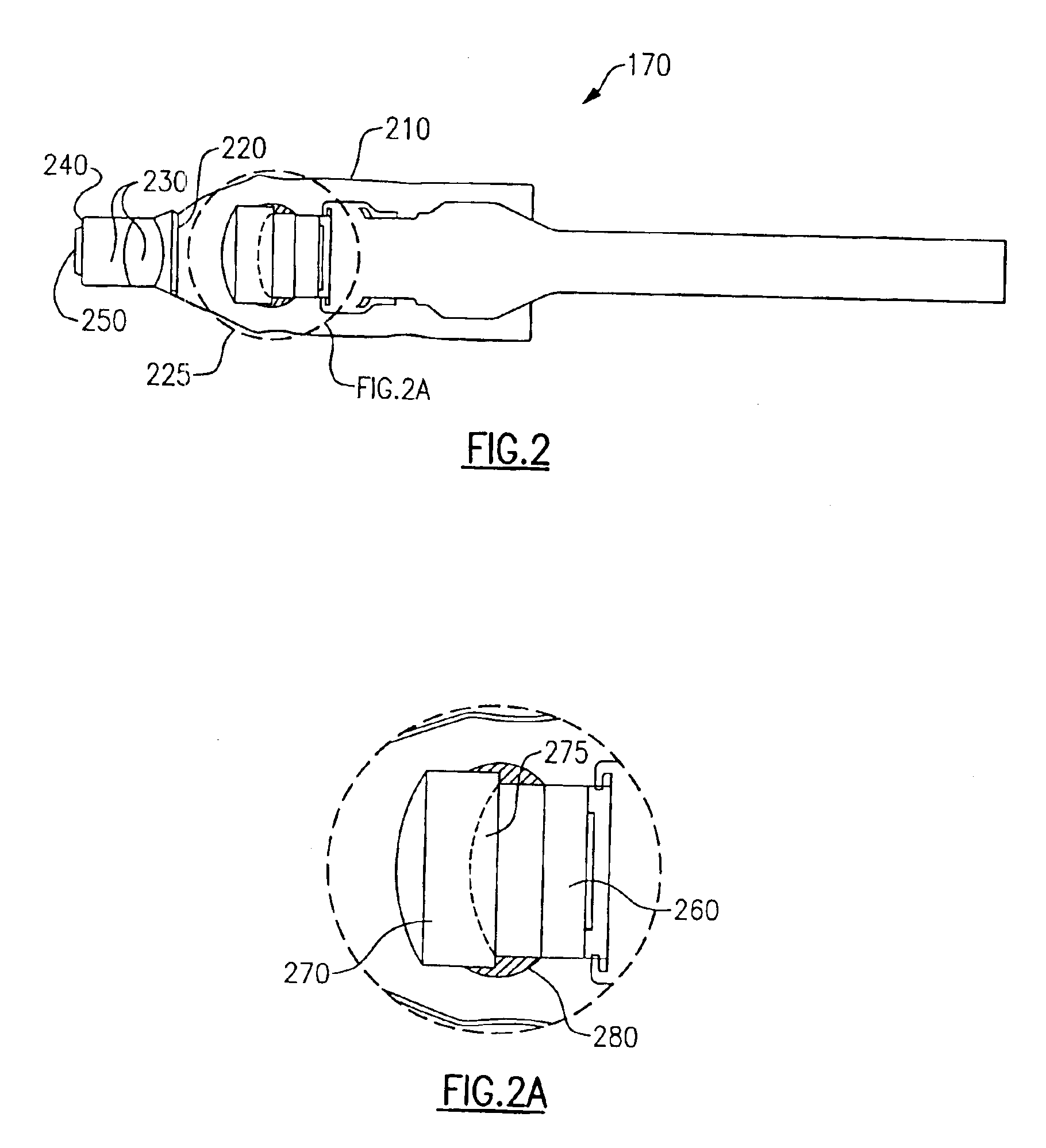
[0019]Referring to FIG. 1, a typical imaging device 100 (a boroscope in the illustrative embodiment) according to the invention is illustrated, such as is sold by Everest VIT® of Flanders, N.J. Such a device could include, as shown in the illustrative embodiment, a portable shipping / operating case 110, that includes a power supply 120 for the device and a light source, such as a metal halide arc lamp (not shown). The shipping / operating case 100 is shown in operative communication with a handpiece 140 by means of a cable 130. The handpiece 140 can include, by way of example, an LCD monitor 150 (which displays images seen by the imaging...


PUM


Abstract

Devices and methods for protecting components of imaging devices are provided. In the illustrative embodiment, a plano-concave protective cover is provided which is bonded to an imager window by applying a thick, quick-setting adhesive to the exterior of the cover and of the imager window.

Description

CROSS REFERENCE TO RELATED APPLICATIONS[0001]None.FIELD OF THE INVENTION[0002]The invention relates generally to protective covers for imaging devices.BACKGROUND OF THE INVENTION[0003]Electronic-type imaging devices of the type used, for example, in microscopes, telescopes, camcorders, thermal imagers, digital cameras, and especially with digital inspection systems (e.g., borescopes, and endoscopes), often are subjected to harsh physical operating conditions, and must embody a degree of survivability, in terms of mechanical durability, temperature tolerance, etc., which exceeds that required for similar electronics designed to operate in more benign environments, such as in clean rooms and climate-controlled office environments. In addition, these “hearty” imaging devices must be protected against environmental debris, such as dirt, dust, chemicals, and corrosive fluids, which might damage the optical elements (typically located in a tip of the imaging device) associated with the im...

Claims


Application Information

Patent Timeline
Patent Type & Authority Patents(United States)
IPC IPC(8): H04N5/225
CPCH04N5/2254H04N23/52
Inventor SCHIEFER, EUGENE C.
Owner GE INSPECTION TECH LP
Why Eureka
Try Eureka