Method for correcting a rotary large-breadth optical satellite sensor

An optical satellite and correction method technology, applied in the aerospace field, can solve problems such as difficult and high-precision stitching, achieve high-quality follow-up applications, solve complex imaging mechanisms, and eliminate image distortion.

Active Publication Date: 2020-09-01
INNOVATION ACAD FOR MICROSATELLITES OF CAS +1
View PDF7 Cites 4 Cited by
  • Summary
  • Abstract
  • Description
  • Claims
  • Application Information

AI Technical Summary

Problems solved by technology

[0004] However, the special imaging method of the rotating large-width opt

Method used


Image

  • Method for correcting a rotary large-breadth optical satellite sensor
  • Method for correcting a rotary large-breadth optical satellite sensor
  • Method for correcting a rotary large-breadth optical satellite sensor

Examples


Embodiment Construction

[0029] In the following description, the present invention is described with reference to various examples. One skilled in the art will recognize, however, that the various embodiments may be practiced without one or more of the specific details, or with other alternative and / or additional methods, materials, or components. In other instances, well-known structures, materials, or operations are not shown or described in detail so as not to obscure the inventive concepts of the present invention. Similarly, for purposes of explanation, specific quantities, materials and configurations are set forth in order to provide a thorough understanding of embodiments of the invention. However, the invention is not limited to these specific details. Furthermore, it should be understood that the embodiments shown in the drawings are illustrative representations and are not necessarily drawn to correct scale.

[0030] In this specification, reference to "one embodiment" or "the embodiment...


PUM


Abstract

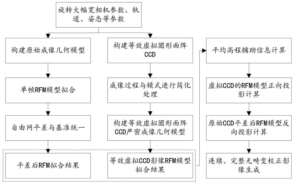
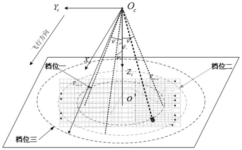
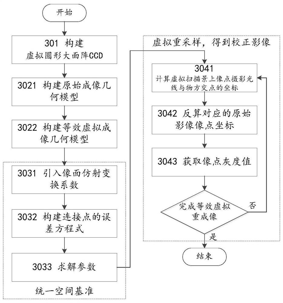
The invention discloses a method for correcting a rotary large-breadth optical satellite sensor, which is used for correcting an imaging load carried by a rotary large-breadth optical satellite according to the following method: firstly, constructing a virtual circular large-area array CCD (Charge Coupled Device) according to the imaging load carried by the rotary large-breadth optical satellite;then, creating an original imaging geometric model and an equivalent virtual imaging geometric model, adopting an RFM model for free network adjustment, and space reference unification; and finally, according to the equivalent virtual imaging geometric model and the RFM model of the original imaging geometric model, carrying out virtual resampling based on object space geometric positioning consistency, and a steady-state equivalent central projection sensor correction image is obtained.

Description

technical field [0001] The invention relates to the field of aerospace technology, in particular to a method for correcting a rotating large-width optical satellite sensor. Background technique [0002] In recent years, with the increasing demand for earth observation, the research and development of remote sensing satellite imaging system has also increased. For remote sensing satellite imaging systems, resolution and width are two extremely important indicators that are difficult to balance. However, the load design of this method is extremely difficult, and it is not conducive to the cost control and miniaturization development of satellites. [0003] In order to deal with this problem and realize large-scale and high-time-efficiency earth observation in a large area, rotational earth imaging has gradually become a new model and has been gradually researched and developed. Among them, the rotating large-width optical satellite is used as a satellite for rotating and ima...

Claims


Application Information

Patent Timeline
IPC IPC(8): G06T3/40G06T5/00
CPCG06T3/4038G06T3/4007G06T5/006G06T2200/32G06T2207/10032G06T2207/30181
Inventor 范城城尹增山胡海鹰刘国华田龙飞李华高爽王旭辉
Owner INNOVATION ACAD FOR MICROSATELLITES OF CAS
Why Eureka
Try Eureka