Electric contact member applying voltage to charger, process cartridge, and image forming apparatus

a contact member and charger technology, applied in the field of image forming apparatus, can solve the problems of localized overcharging or melting of the remaining developing agent image, defective images, and contact charging member may get dirty

Inactive Publication Date: 2005-10-11
CANON KK
View PDF53 Cites 130 Cited by
  • Summary
  • Abstract
  • Description
  • Claims
  • Application Information

AI Technical Summary

Benefits of technology

[0016]It is still another object of the invention to provide an electric contact member, a process cartridge, and an image forming apparatus preventing developing agent collection defect from occurring out of an image carrier or preventing the charging means from getting dirty upon attachments of the developing agent, caused by an improper charge amount of the remaining developing agent on the image carrier.

Problems solved by technology

If such overcharging of the remaining developing agent image occurs, the mirror reflection force between the photosensitive body and the overcharged developing agent becomes too strong, so that the remaining developing agent image cannot be attached even with a contact charging device, cannot be collected with the developing apparatus, and cannot be transferred with a transferring device, and consequently, the remaining developing agent image is adhered to the surface of the photosensitive body, thereby forming defective images.
At the charged portion, the problems of localized overcharging or melting of the remaining developing agent image may occur.
At the inadequate charging portion, the contact charging member may get dirty due to attachment of the developing agent because the remaining developing agent image cannot be charged adequately.
According to various recent needs of users, the above problems are further raised because a large remaining developing agent image occurs as a result of a continuous printing operation of high printing rate images, such as photographic images or multiple developing methods on the photosensitive body in association with rendering the images in multiple colors.

Method used


Image

  • Electric contact member applying voltage to charger, process cartridge, and image forming apparatus
  • Electric contact member applying voltage to charger, process cartridge, and image forming apparatus
  • Electric contact member applying voltage to charger, process cartridge, and image forming apparatus

Examples


Embodiment Construction

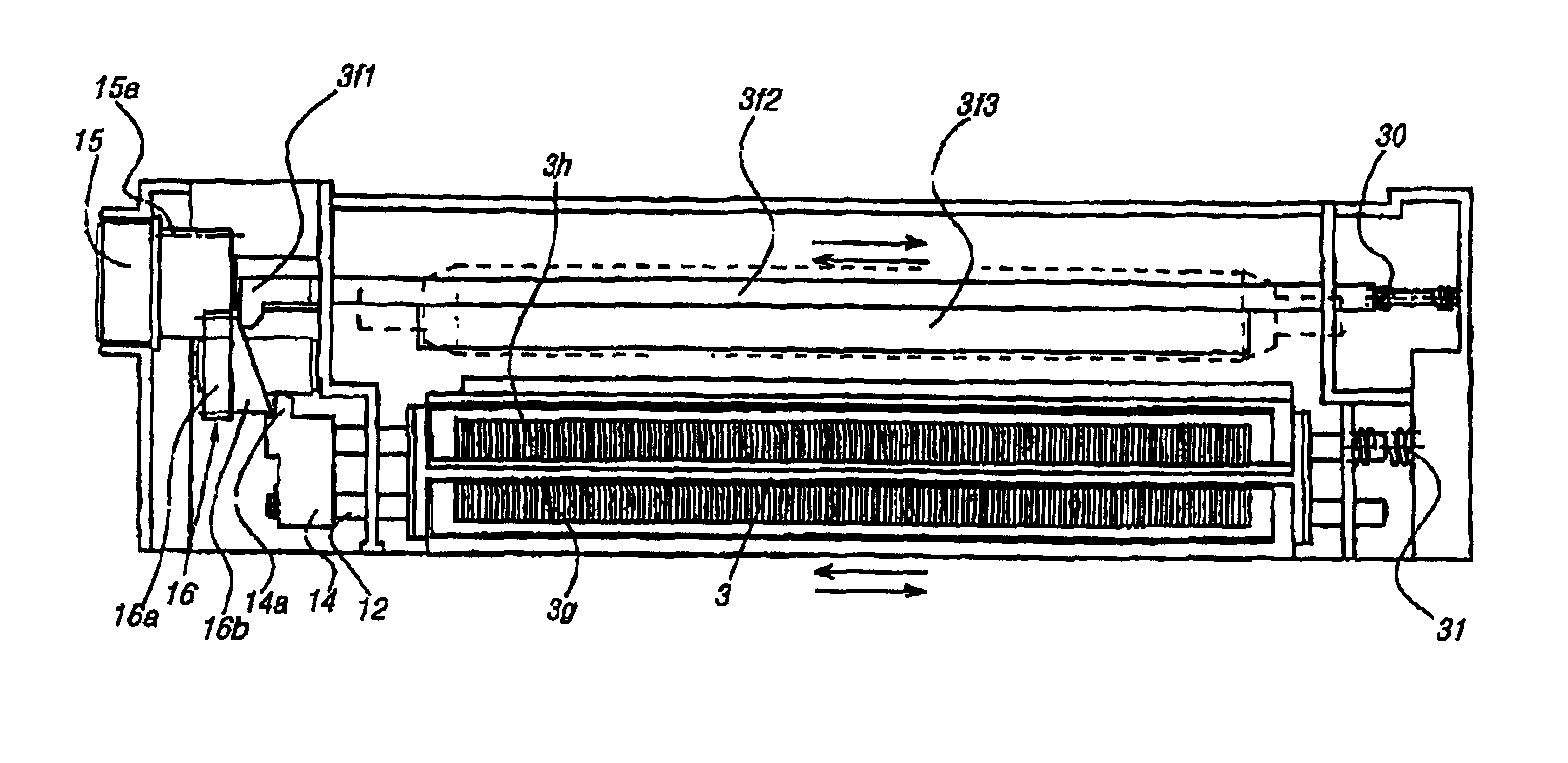
[0028]Now, embodiments of an electric contact member, a process cartridge, and an image forming apparatus, according to the invention are described. In the description below, the term “longitudinal direction” is a direction perpendicular to the conveyance direction of the recording medium and is the same direction to the axial direction of the image carrier. The term “right and left” is the right and left direction when seen from the conveyance direction of the recording medium. The term “up and down” is the up and down direction when the cartridge is mounted.

[Description of the Whole Image Forming Apparatus]

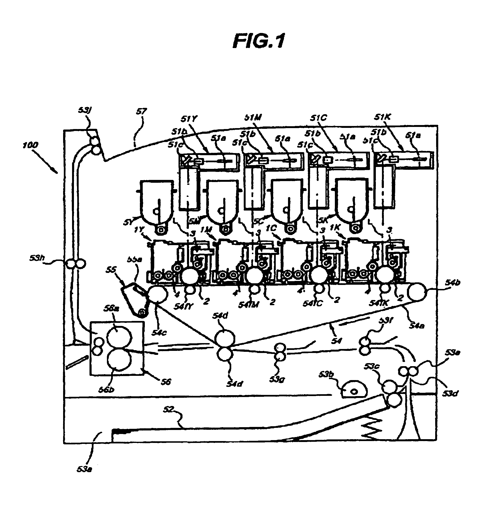
[0029]Referring to FIG. 1, the outline of the whole structure of the image forming apparatus is described. FIG. 1 is an illustration showing the whole structure of a laser beam printer as an embodiment of a multicolor electrophotographic image forming apparatus.

[0030]In the image forming portion of the multicolor laser beam printer, four process cartridges 1Y, 1M, 1C, 1K (yellow...


PUM


Abstract

The present invention relates to an electric contact member applying a voltage from a voltage applying device to a charger reciprocally moving in a longitudinal direction of an image carrier. The member includes a securing portion electrically connected to a side of the voltage applying device, a moving portion reciprocally movable and connected electrically to a side of the charger, and a buffer portion formed between the securing portion and the moving portion.

Description

BACKGROUND OF THE INVENTION[0001]1. Field of the Invention[0002]This invention relates to an image forming apparatus such as, e.g., electrophotographic copier, and electrophotographic printer, to a process cartridge detachably attached to the image forming apparatus body, and to an electric contact member suitable to be used in those apparatuses.[0003]Herein, the image forming apparatus is to form images on recording media using electrophotographic image forming process. The image forming apparatus includes, e.g., electrophotographic copier, electrophotographic printer (LED printer, laser beam printer, etc.), electrophotographic facsimile machine, and electrophotographic word processor.[0004]The process cartridge is made of a cartridge integrating an electrophotographic photosensitive drum as an image carrier with at least one of charging means, developing means, and cleaning means, and the cartridge is used as detachably attached to the image forming apparatus body.[0005]2. Descrip...

Claims


Application Information

Patent Timeline
Patent Type & Authority Patents(United States)
IPC IPC(8): G03G15/02G03G15/00G03G21/00
CPCG03G15/0233G03G2221/183
Inventor FUJITA, AKIYOSHINUMAGAMI, ATSUSHIUENO, TAKAHITO
Owner CANON KK
Why Eureka
Try Eureka