[0012]Under the aforementioned technical background, the present invention aims to provide a method, etc., for measuring a shape of a tubular body in a simple manner with high precision.
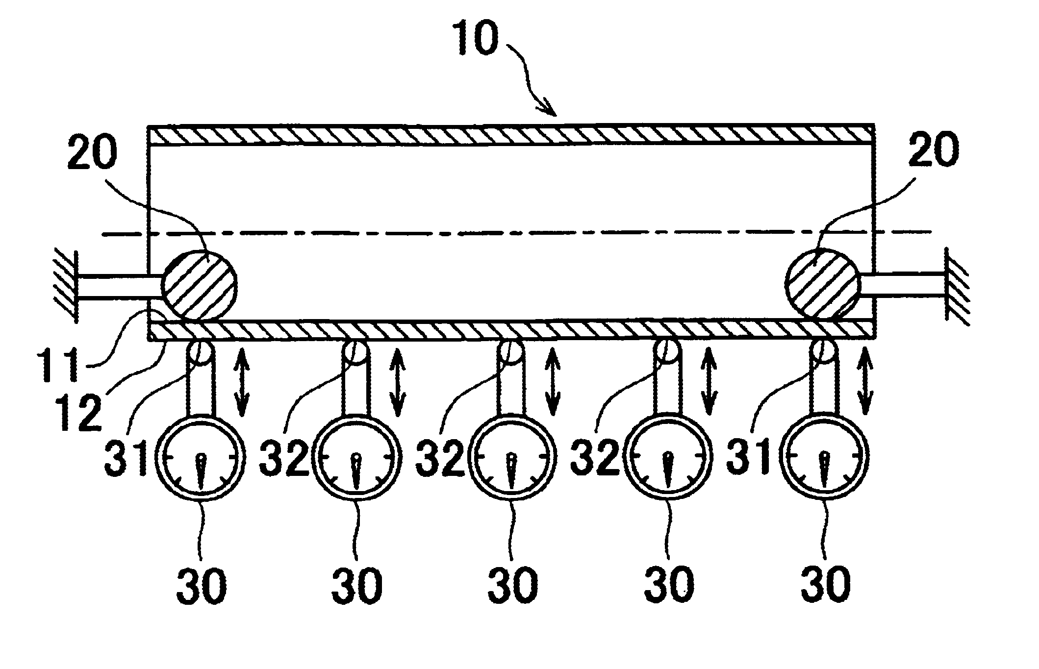
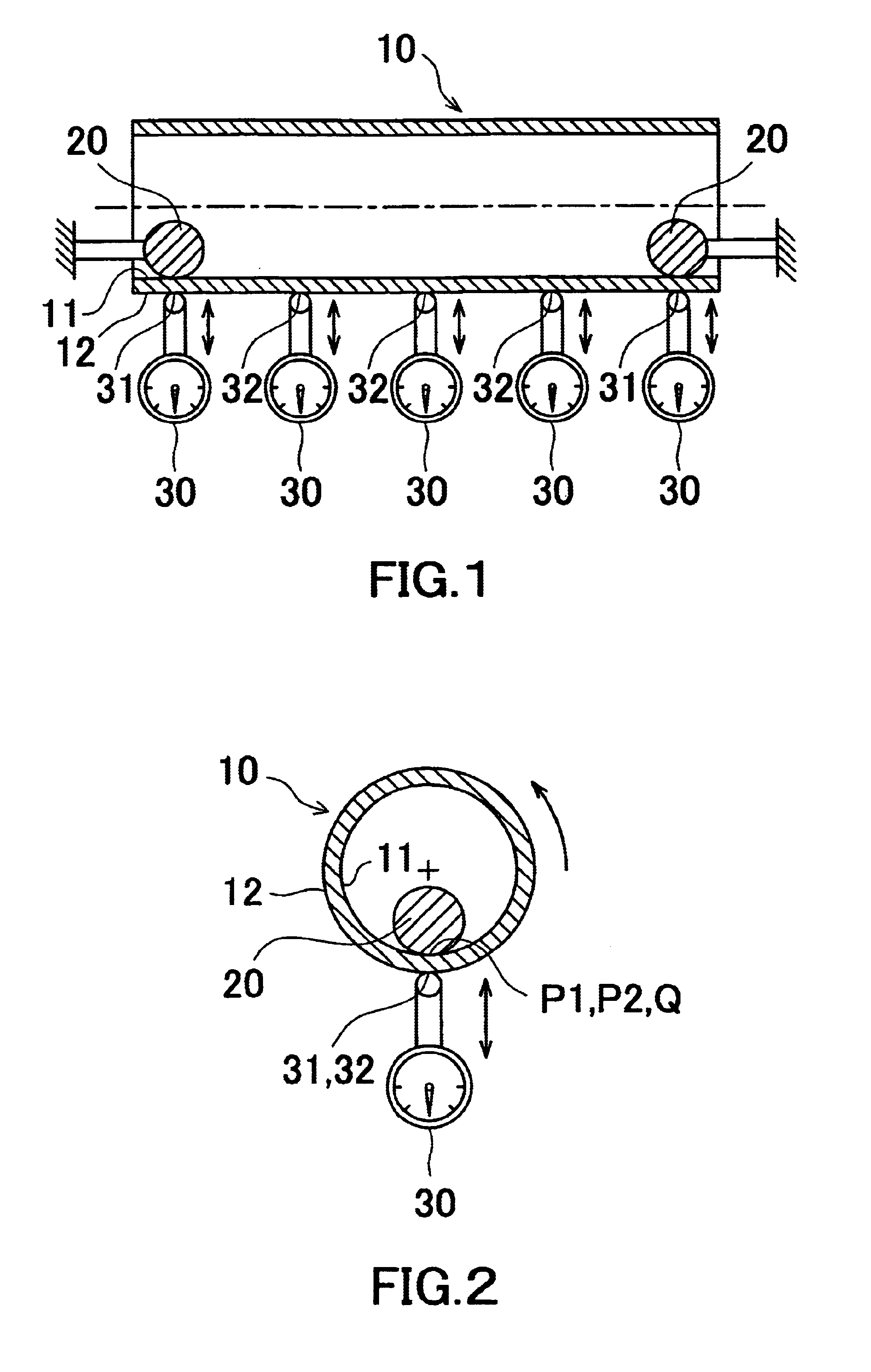
[0018]According to such an apparatus for measuring a shape of a tubular body, the deflection of the external peripheral surface with respect to the internal peripheral surface as a benchmark, i.e., the deflection of the external peripheral surface to which the influence of uneven thickness of the tubular body is reflected, can be measured. Therefore, it becomes possible to perform measurement of a tubular body whose internal peripheral surface is to be rotatably supported in the actual use in a condition similar to the actual use condition. Furthermore, since the deflection of the external peripheral surface to be measured is reflected by the influence of uneven thickness, it is possible to prevent the accumulation of device differences and / or a request of excessive quality which may occur in the case of separately measuring the thickness of the tubular body. Furthermore, since the deflection of the external peripheral surface to be measured reflects the influence of uneven thickness, the time required to conduct the measurement can be shortened. Furthermore, since the apparatus has a simple structure in which the radial displacement of the external peripheral surface of the tubular body is measured in a state in which the pair of reference portions is in contact with the internal peripheral surface of the tubular element, the accumulation of measurement errors can be decreased as small as possible, and the shape measurement can be attained with high precision. Furthermore, since it only requires to bring the reference portions into contact with the internal peripheral surface side, the apparatus can be preferably applied to shape measurement of a tubular body with a smaller inner diameter. Furthermore, since the weight of the tubular body is supported from the lower side thereof by the supporting rollers, the contact pressure between the tubular body and the pair of contacting portions can be controlled appropriately irrespective of the weight of the tubular body, which enables high reliable shape measurement. Furthermore, since two supporting rollers are disposed at both sides of the tubular body, respectively, the axial position of the tubular body and the attitude of the tubular body can be stabilized, resulting in a stable rotational movement of the tubular body. As a result, high accuracy of measurement can be attained. Furthermore, since the supporting rollers carry out a function of supporting the weight of the tubular body and a function of positioning the axis of the tubular body, the number of members that contact the tubular body can be decreased. This eliminates factors of errors, contributing to accurate shape measurement, which enables to obtain high reliability of shape measurement and decrease the possibility of damages to the tubular body.
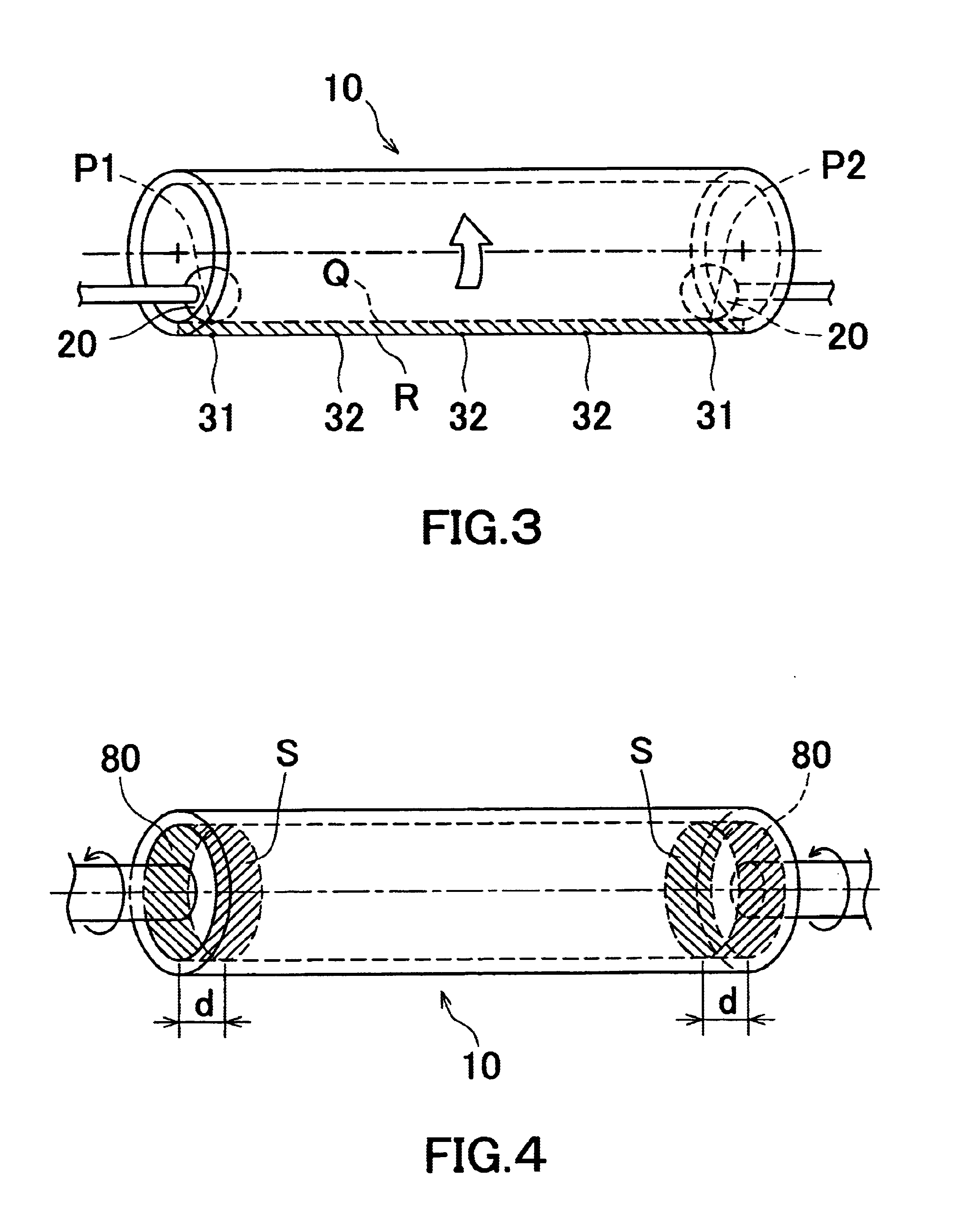
[0020]According to such a method for measuring a shape of a tubular body, the radial displacement of the external peripheral surface can be detected, not in a state in which the tubular body is in an untouched state, but in a state in which both of the side end portions are temporality corrected by the correcting rollers. Therefore, the shape of the tubular body can be measured under the condition similar to the actual use condition in which the cross-sectional shape of both of the side end portions are deformed into an appropriate shape. Accordingly, the shape of the tubular body in actual use can be measured with a high degree of accuracy, which in turn can prevent a request of excessive quality to secure necessary shape accuracy which is demonstrated in actual use.
[0022]According to such a method for measuring a shape of a tubular body, the radial displacement of the external peripheral surface can be detected, not in a state in which the tubular body is in an untouched state, but in a state in which both of the side end portions are temporality corrected by the correcting rollers. Therefore, the shape of the tubular body can be measured under the condition similar to the actual use condition in which the cross-sectional shape of both of the side end portions are deformed into an appropriate shape. Accordingly, the shape of the tubular body in actual use can be measured with a high degree of accuracy, which in turn can prevent a request of excessive quality to secure necessary shape accuracy which is demonstrated in actual use. Furthermore, the correcting rollers for correcting both of the side end portions of the tubular body serves as supporting rollers for maintaining the posture of the tubular body by supporting the tubular body at the time of measuring the shape of the tubular body. Therefore, by setting the tubular body to a shape measuring position where the tubular body comes into contact with the correcting rollers, the end portion correction and the shape measurement can be performed continuously, resulting in excellent operation efficiency. Furthermore, since the number of contacts caused between the tubular body and the rollers supporting the tubular body can be decreased, the possibility of damages caused by the contacts of the tubular body against the rollers or the like can be decreased. Furthermore, since the tubular body whose shape was measured as explained above has already been corrected in cross-sectional shape of the end portions, an operation of press fitting of a flange or the like can be performed easily and assuredly. Thus, it becomes possible to prevent generation of defective products caused by pressing a flange or the like into an uncorrected non-circular end portion in a slanted manner.
[0024]According to such a method for measuring a shape of a tubular body, the central axis position of the pair of expandable clamps is located almost at the center of a circle formed by the internal peripheral surface of the tubular body. By rotating the tubular body about the central axis of the pair of expandable clamps, it becomes possible to realize a rotating status extremely similar to a rotating status of the tubular body in actual use which is rotated with the internal peripheral surface supported. Therefore, the action of the tubular body detected when rotating is almost equivalent to the action of the tubular body in actual use. Concretely, the detected radial displacement of the external peripheral surface corresponds to the deflection generated in actual use. In detail, the radial displacement of the external peripheral surface to be detected corresponds to the deflection of the external peripheral surface with respect to the near central of a circle formed by the internal peripheral surface at the vicinity of both end portions of the tubular body. Therefore the radial displacement reflects all influences such as the curvature, the uneven thickness, the cross-sectional shape (circularity), etc. of the tubular body. Furthermore, since the deflection of the external peripheral surface to be measured reflects the influence of uneven thickness, it is possible to prevent the accumulation of device differences and / or a request of excessive quality which may occur in the case of separately measuring the thickness of the tubular body. Furthermore, since the deflection of the external peripheral surface to be measured reflects the influence of uneven thickness, the time required to conduct the measurement can be shortened. Furthermore, since the pair of expandable clamps contact the internal peripheral surface of the tubular body along the entire circumference thereof, the central axis of the pair of expandable clamps can be assuredly positioned at the center of a circle formed by the internal peripheral surface of the tubular body, which can realize a status similar to a rotating status in actual use. Furthermore, since the pair of expandable clamps contact the internal peripheral surface of the tubular body along the entire circumference thereof, even if the expandable clamps make contact with the tubular body with larger pressing force, the pressing force can be distributed in the circumferential direction almost evenly, contributing to accurate shape measurement. Furthermore, it is only requested to insert the pair of expandable clamps inside the tubular body, expand them therein and then rotate the tubular body together with the expandable clamps to detect the displacement of the external peripheral surface. Therefore it is possible to perform the measurement with a simple structure and obtain high accuracy of shape measurement by decreasing the accumulation of measurement errors as small as possible.

