Roller cone drill bit legs

a technology of roller cone drill bit and spherical head, which is applied in the field of drill bit, can solve the problems of high erosion rate of the shirttail portion of typical prior art roller cone drill bit, difficult to avoid contact, and ineffective reduction of type of wear resistance structur

Inactive Publication Date: 2005-10-18
SMITH INT INC
View PDF4 Cites 39 Cited by
  • Summary
  • Abstract
  • Description
  • Claims
  • Application Information

AI Technical Summary

Problems solved by technology

In certain circumstances, such contact is difficult to avoid.
In certain drilling operations, such as with drill strings which include steerable mud motors and the like, it has been observed that the shirttail portion of typical prior art roller cone drill bits is subject to high rates of erosion due to fluid flow past the shirttail, in addition to any abrasive wear which sometimes may result from the previously described wall contact.
These type of wear resistance structures are not particularly effective in reducing wear caused by erosion because they only serve to prevent contact between surfaces.
Typical hardfacing thermal application techniques tend to raise the temperature of the applied-to structure so a degree which makes the use of such techniques impracticable for roller cone drill bits because of possible damage to the seals and lubricant, at least.
Such techniques when used prior to assembly of the roller cones to the leg may also result in some changes to the fracture toughness of the leg material, and have therefore not been widely used.
In many cases, erosion on the shirttail is not a problem, meaning that erosion damage to the shirttail occurs at such slow rates relative to wear of the bearing structure and cutting elements on the roller cones, as to make hardface application to the shirttail on all drill bits uneconomical.

Method used


Image

  • Roller cone drill bit legs
  • Roller cone drill bit legs
  • Roller cone drill bit legs

Examples


Embodiment Construction

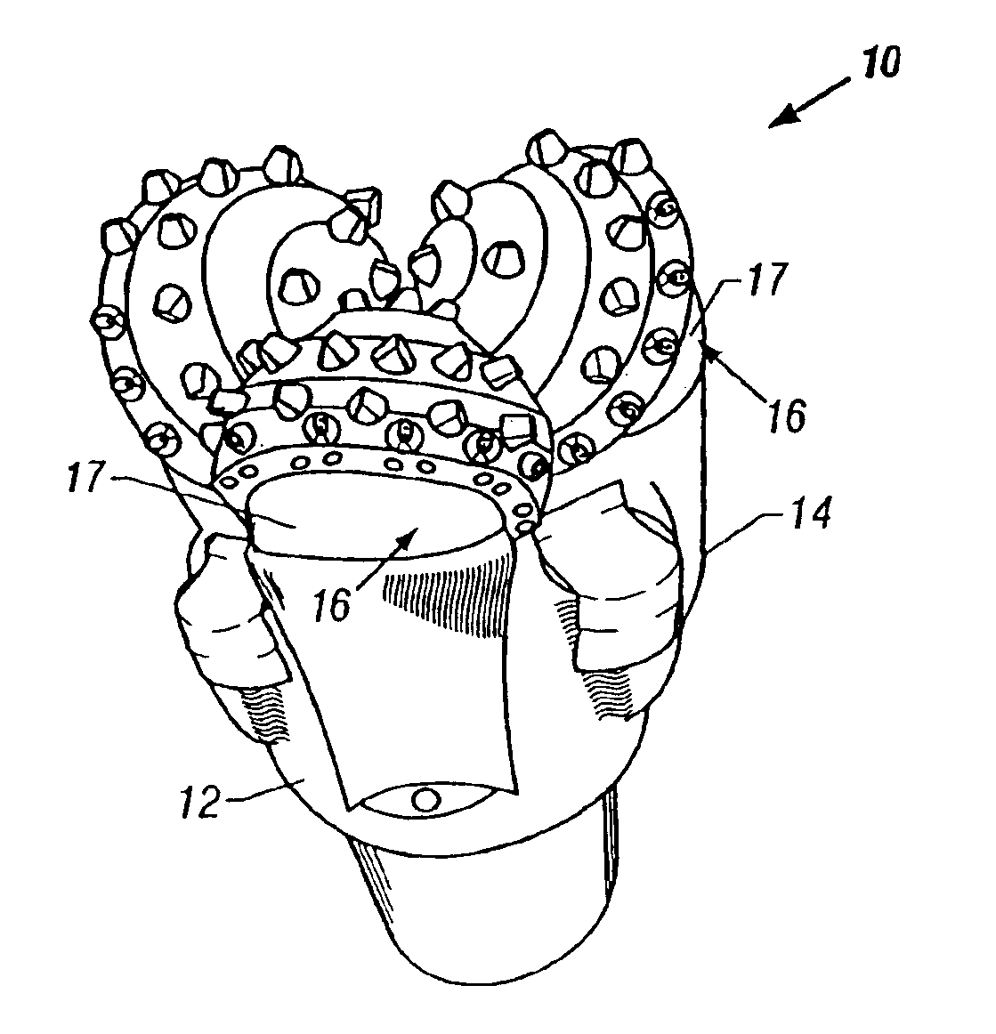
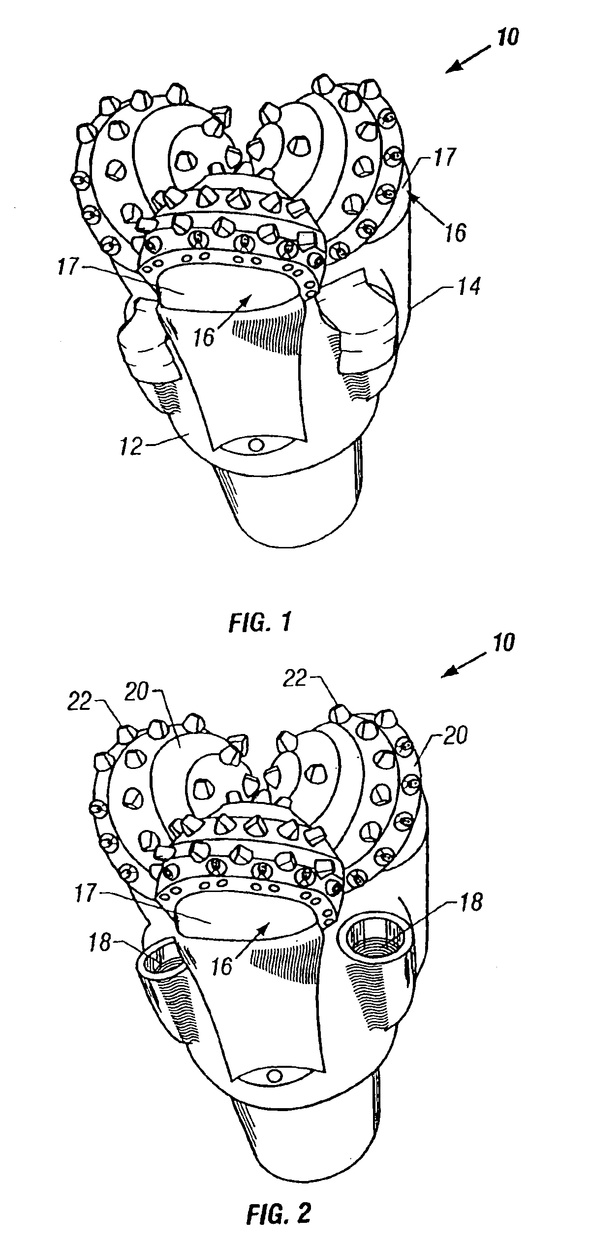
[0015]FIGS. 1 and 2 show a side view of a roller cone drill bit made according to one aspect of the invention. The drill bit 10 includes a bit body 12 made from steel or similar metal typically used for roller cone bit bodies. The bit body 12 includes one or more legs 14, and typically includes three such legs, depending from the bit body 12 as is conventional for roller cone drill bits. Each leg 14 includes a roller cone 20 rotatably mounted thereon. Each cone 20 is made from steel or similar metal known in the art for use as a roller cone. The roller cones 20 include thereon at selected positions, a plurality of cutting elements 22, which may be inserts, milled teeth or any other similar structure known in the art for use as a cutting element on a roller cone drill bit. The drill bit 10 also includes jets 18 inserted into appropriately formed recesses (not shown separately) in the bit body 12.

[0016]In a roller cone drill bit made according to one aspect of the invention, each leg ...


PUM

PropertyMeasurementUnit
thicknessaaaaaaaaaa
thicknessaaaaaaaaaa
pressureaaaaaaaaaa

Abstract

A method is disclosed for applying hardfacing to a shirttail portion of a roller cone drill bit, including masking around the shirttail portion of the bit and operating a high pressure / high velocity oxygen fuel torch to apply the hardfacing to the shirttail portion.

Description

CROSS-REFERENCE TO RELATED APPLICATIONS[0001]This application is a divisional application of U.S. patent application Ser. No. 10 / 114,833 entitled “METHOD FOR HARDFACING ROLLER COVE DRILL BIT LEGS,” filed Apr. 3, 2002.BACKGROUND OF THE INVENTION[0002]1. Field of the Invention[0003]The invention relates generally to the field of drill bits used to bore holes through earth formations. More particularly, the invention relates to methods and structures for improving the durability of roller cone drill bits.[0004]2. Background Art[0005]Drill bits used to bore drill holes or wellbores through earth formations include roller cone bits. Typical roller cone bits include a bit body made from steel or similar material. The bit body includes one or more, and typically three, legs which depend from the bit body. The bit body is usually adapted to be threadedly or otherwise coupled to a drilling tool assembly (“drill string”) which rotates the bit body during drilling. The legs include a bearing j...

Claims


Application Information

Patent Timeline
Patent Type & Authority Patents(United States)
IPC IPC(8): C23C30/00C23C4/00E21B10/46E21B10/50
CPCC23C4/00C23C30/005E21B10/50
Inventor CROWE, JOHN RAMSAYGREIG, ANGUSHAMILTON, ROBERTFARQUHAR, GARYANGUS, KEVIN
Owner SMITH INT INC
Why Eureka
Try Eureka