

Air cleaner for engines
a technology for cleaning air and engines, applied in machines/engines, combustion-air/fuel-air treatment, separation processes, etc., can solve problems such as engine failure, foreign matter contaminating the carburetor, and weeds, dust and pebbles are usually present, and achieve the effect of contaminating the carburetor
- Summary
- Abstract
- Description
- Claims
- Application Information
AI Technical Summary
Benefits of technology
Problems solved by technology
Method used
Image

Examples
Embodiment Construction
[0021]The following descriptions are of exemplary embodiments only, and are not intended to limit the scope, applicability or configuration of the invention in any way. Rather, the following description provides a convenient illustration for implementing exemplary embodiments of the invention. Various changes to the described embodiments may be made in the function and arrangement of the elements described without departing from the scope of the invention as set forth in the appended claims.
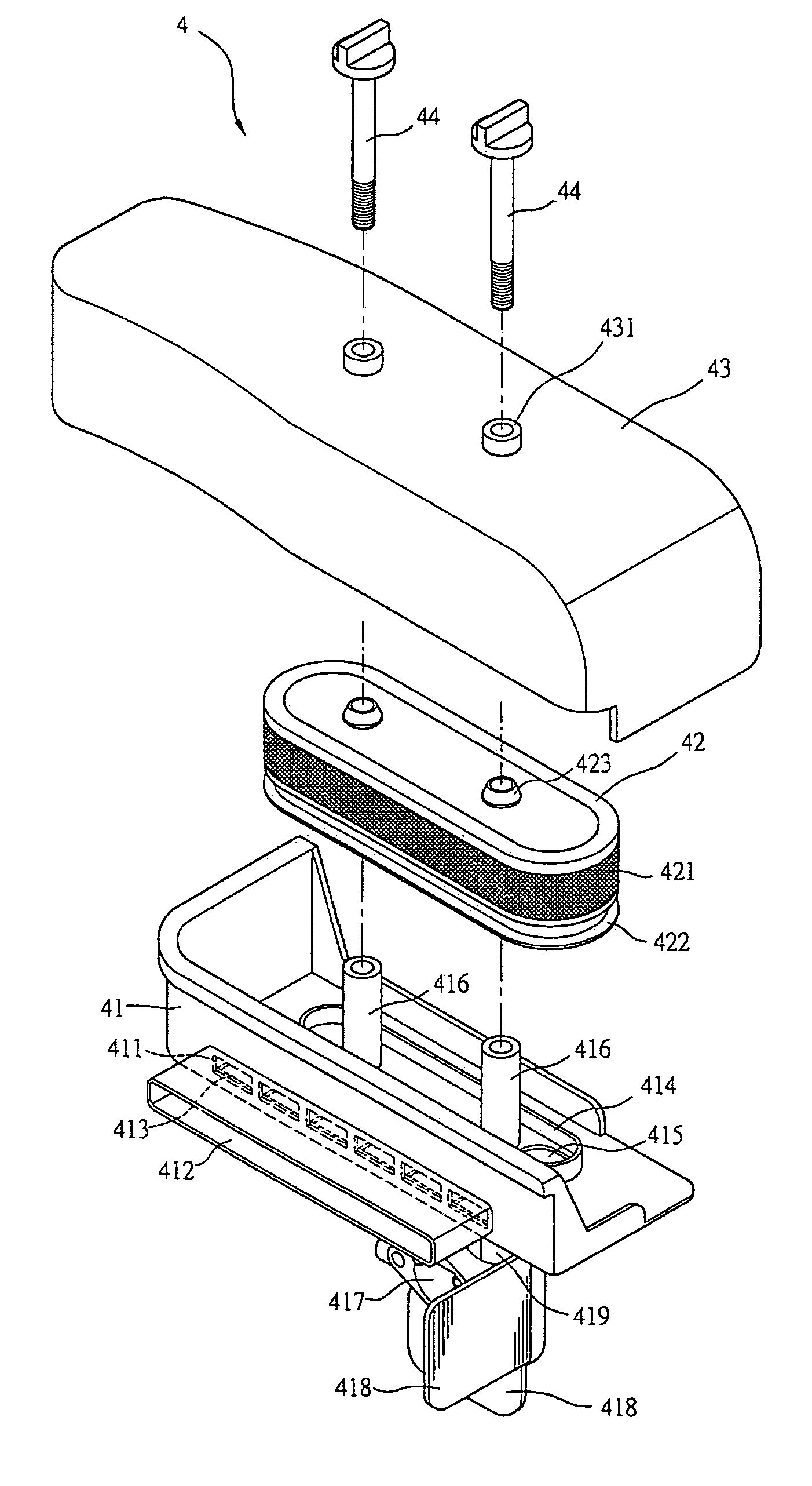
[0022]Referring to FIGS. 4 and 6, an air cleaner 4 adapted to an engine 61 is essentially comprised of a case 41, an air cleaner element 42 and a cover 43. The case 41 and the cover 43 define a space to accommodate the air cleaner element 42. An air inlet 411 is provided on the side at where close to a carburetor 5. A hollow tube 412 extends externally from the peripheral of the case 41. A supplementary air inlet 413 is provided at the bottom of the case 41 to admit air and to function as a drain...
PUM
| Property | Measurement | Unit |
|---|---|---|
| power | aaaaa | aaaaa |
| speed | aaaaa | aaaaa |
| circumference | aaaaa | aaaaa |
Abstract
Description
Claims
Application Information