
Disposable mask assembly with exhaust filter and valve disc and method of assembling same

a mask and valve disc technology, applied in the field of face mask assembly, can solve the problems of inability to completely accept prior art devices, a multitude of moving parts, and a complex filter system, and achieve the effects of reducing the number of masks

Active Publication Date: 2013-01-01
RESPAN PRODS
View PDF71 Cites 23 Cited by
  • Summary
  • Abstract
  • Description
  • Claims
  • Application Information

AI Technical Summary

Benefits of technology

The mask assembly effectively reduces the release of patient exhaled gases and contaminants into the atmosphere, is easily interchangeable with different filters, and simplifies assembly and manufacturing, while ensuring a continuous oxygen supply and safe inhalation.

Problems solved by technology

However, these prior art devices are not entirely acceptable for a variety of reasons.
Consequently, the filter system is comparatively complex and utilizes a multitude of moving parts.
Moreover, the interchangeability of the mask with multiple filters is relatively limited.
Therefore, healthcare personnel administering treatments to patients are exposed to free airborne medication mist which potentially causes infectious diseases.
Therefore, healthcare professionals and emergency personnel administering treatments to patients are exposed to airborne contaminated oxygen particles.
In addition, should the nasal portion of the mask fail where the patient is inhaling pure oxygen, there is a chance of suffocation because the valve disc would block any air from passing from the environment through the apertures since the valve disc completely surrounds the apertures.

Method used


Image

  • Disposable mask assembly with exhaust filter and valve disc and method of assembling same
  • Disposable mask assembly with exhaust filter and valve disc and method of assembling same
  • Disposable mask assembly with exhaust filter and valve disc and method of assembling same

Examples


second embodiment

of FIGS. 5-13

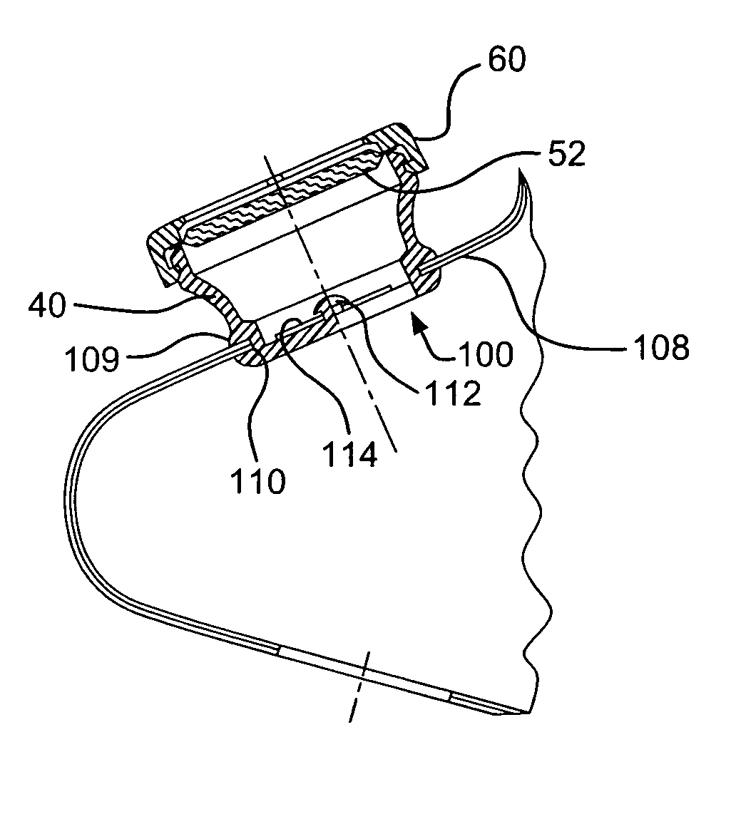
[0049]In a second embodiment, illustrated in FIGS. 5-13, the filter housing 40 of the first embodiment is modified to accommodate a non-rebreather mask. More specifically, the bottom 100 of the filter housing 40 is modified with the addition of a valve disc 114 that partially restricts the flow of a gas into and out of the mask during inhalation and exhalation by the patient wearing the mask.

[0050]The filter bottom 100 includes a substantially planar frame 102 having a substantially cross-shaped surface 104 with a circular edge 106, surface 104 forming a valve seat for valve disc 114. A plurality of openings or apertures 116 are formed in the cross-shaped surface 104 and extend between the cross-shaped surface 104 from the circular edge 106, as seen in FIGS. 6-9. The apertures 116, as seen in FIG. 9, have an outer edge closest to the circular rim 102 and are arrowhead-shaped with the point 118 of the arrow facing the center 120 of the frame. The exterior side 108 of the...


PUM


Abstract

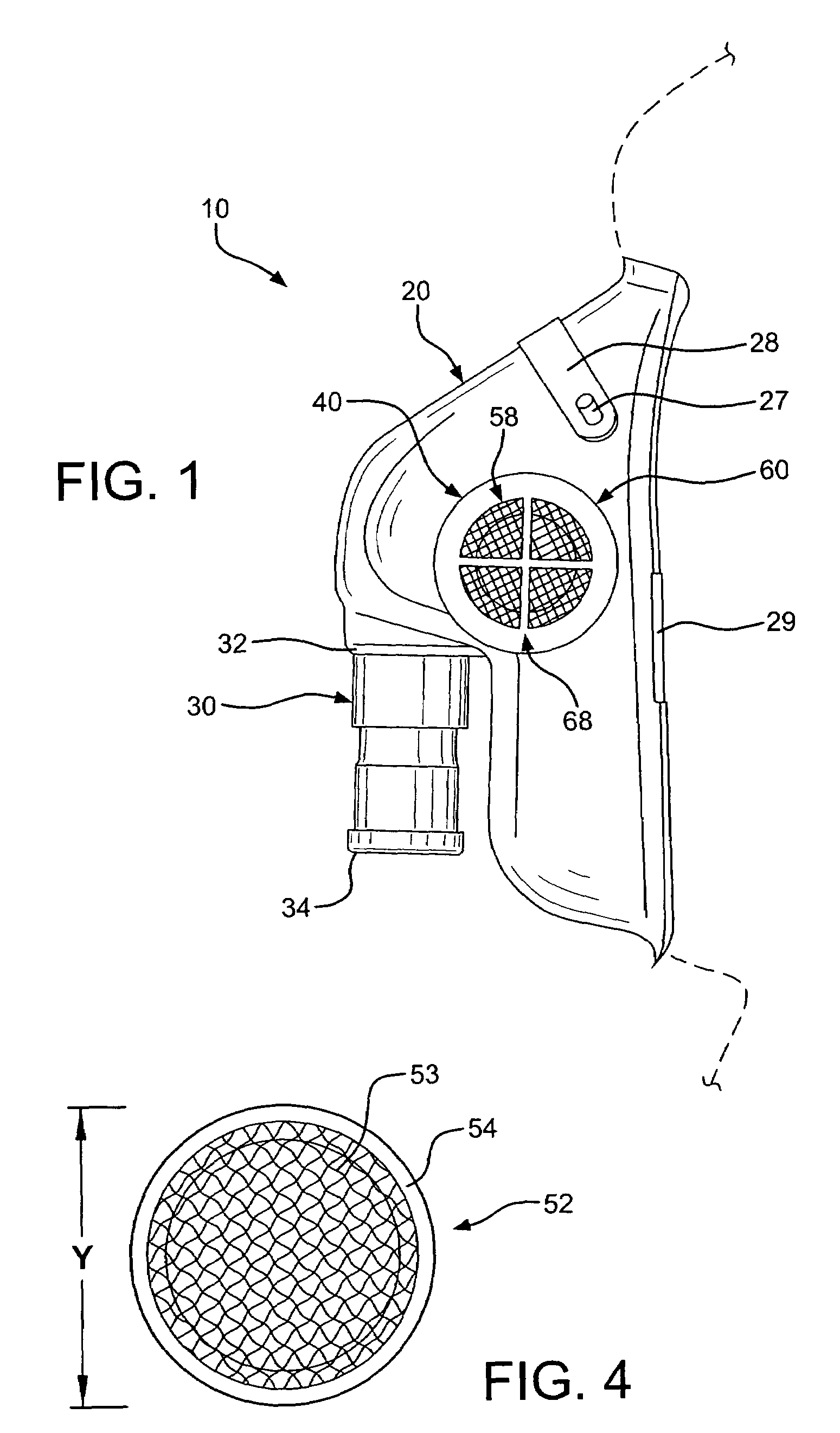
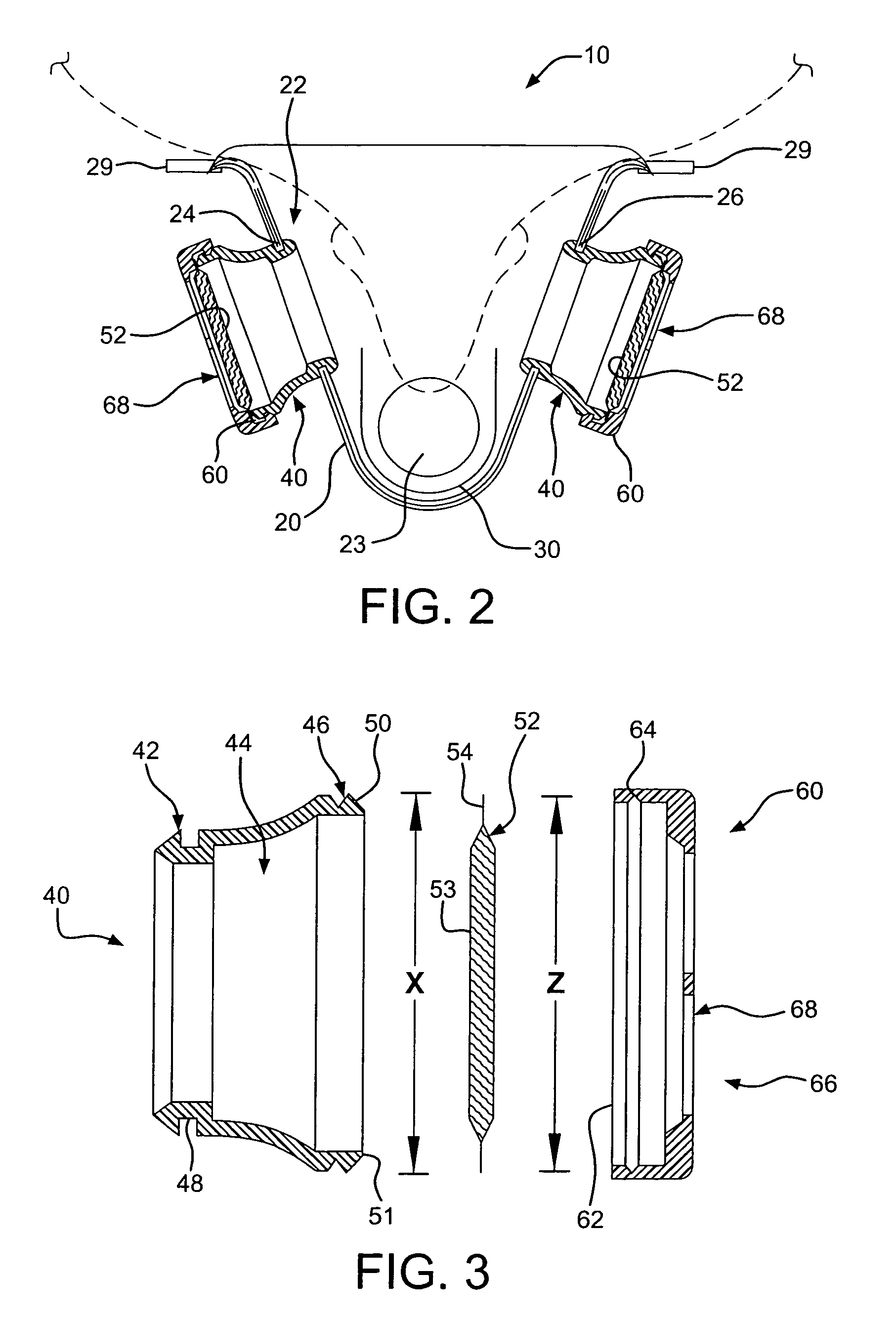
A face mask assembly and method of assembling a face mask is provided for a patient that includes a face piece sized to fit over the patient's nose and mouth. The face mask assembly forms a mask chamber between the face piece and the patient's nose and mouth. An inhalation adapter is coupled to the face piece to deliver medication to the chamber. A filter housing is coupled to the face piece and includes a flange section that defines a passageway to connect the mask chamber and the flange section. A filter is positioned in the filter housing. A cover is coupled to the flange section and has an exhalation opening or vent to allow gases from the mask chamber to pass through the filter and escape from the passageway to the atmosphere. In a second embodiment, the filter housing is modified by providing a frame adjacent the bottom with a cross-shaped structure and a retainer button attached to the housing. A valve disc is provided between the retainer button and frame adapted to allow gases from the mask chamber around the valve disc towards the filter. When a patient inhales oxygen through the nasal portion, the valve disc moves towards the mask and partially covers a plurality of apertures to partially block additional air from entering the chamber. When a patient exhales contaminated oxygen, the valve disc moves towards the retainer button to allow a maximum amount of air through the apertures towards the filter.

Description

CROSS REFERENCE TO RELATED APPLICATION[0001]This application is a continuation-in-part of and claims the benefit of U.S. patent application Ser. No. 11 / 269,678, filed Nov. 9, 2005 now U.S. Pat. No. 7,559,323, the subject matter of which application is hereby incorporated herein by reference in its entirety.FIELD OF THE INVENTION[0002]The present invention relates to a face mask assembly to filter a patient's exhalation and allow a minimum inhalation if necessary. More particularly, the present invention relates to a face mask assembly including a face piece having a filter positionable between a filter housing and a snap-fitting cover with an exhalation vent. The filter housing also is snap-fitted to the mask face piece. The filter housing includes a valve disc attached to the portion of the housing closest to the mask piece to prevent a large volume of external air from entering the mask when a patient inhales. The flexible discs are adjacent to the mask piece to permit air to be r...

Claims


Application Information

Patent Timeline
Patent Type & Authority Patents(United States)
IPC IPC(8): A62B18/08
CPCA61M16/06A61M16/1065A62B23/02
Inventor HACKE, GERHARD A.HACKE, CORNEL C.
Owner RESPAN PRODS
Learn More