Speaker

a loudspeaker and speaker technology, applied in the field of loudspeakers, can solve the problems of deteriorating sound, unable to completely prevent the generation of abnormal sounds, and abnormal noise, so as to improve symmetrical vibration, reduce frictional resistance with the shaft, and improve flexibility.

Inactive Publication Date: 2006-12-12
PANASONIC CORP
View PDF13 Cites 23 Cited by
  • Summary
  • Abstract
  • Description
  • Claims
  • Application Information

AI Technical Summary

Benefits of technology

[0013]A speaker of the present invention is further provided with a damper in addition to the above-described structures of the present invention. This configuration prevents a leap phenomenon at great amplitudes and improves symmetrical vibration between the up-side and down-side amplitudes, which drawbacks are beyond the control of a combination of only the shaft and the bearing, although the configuration might be slightly inferior in flexibility to a speaker with no damper.
[0014]A speaker of the present invention is further provided with a bearing cover disposed around the through hole on the upper surface of the top plate. This configuration prevents the magnetic flui

Problems solved by technology

Under such a state, the vibration system readily causes a rolling motion, which makes the voice coil 12 physically contact with yoke 2 or top plate 4 in the magnetic gap and generate

Method used


Image

  • Speaker
  • Speaker
  • Speaker

Examples


first embodiment

[0025]A speaker in accordance with an exemplary embodiment of the present invention is described referring to FIG. 1 and FIG. 2.

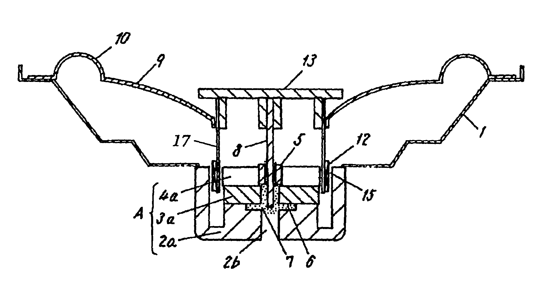
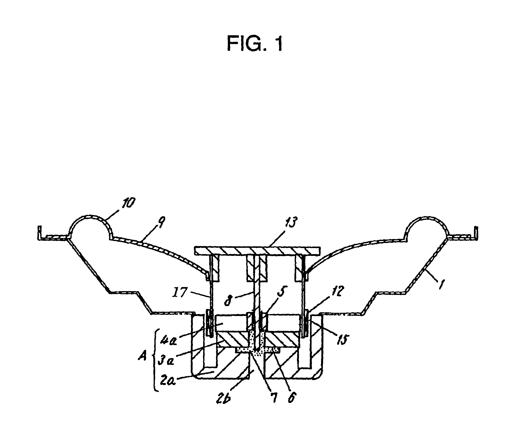
[0026]In a speaker of the present invention, an inner magnet type magnetic circuit A is formed of a yoke 2a, a magnet 3a and a top plate 4a, and the magnetic circuit is provided with a through hole 2b at the center, as shown in FIG. 1. A frame 1 is fixed on the yoke 2a of magnetic circuit A. A diaphragm 9 and an edge 10 are fixed on the frame 1. A bobbin 17 of a voice coil 12 is fixed to an inner circumference of the diaphragm 9, and the voice coil 12 is supported in a magnetic gap 15 formed by the yoke 2a and the top plate 4a. A center cap 13 is fixed on the bobbin 17 at the top edge, so as to be coaxial with the axis of the bobbin 17.

[0027]A bearing 5 is fixed to be coaxial with the axis of the through hole 2b. A shaft 8 is fixed at the top end to a center of the center cap 13, and supported by the bearing 5 so that it can move up and down.

[0028]The yoke ...

second embodiment

[0034]A speaker in accordance with a second exemplary embodiment of the present invention is described referring to FIG. 3 and FIG. 4. Description is made focusing on a point of difference from the first embodiment.

[0035]FIG. 3 is a cross-sectional view of a speaker in the present embodiment, while FIG. 4 is a characteristics chart showing a relation between maximum amplitudes and frequency characteristics. As FIG. 3 shows, the speaker of the present embodiment is provided with a damper 11, which is fixed at the outer circumference to the frame 1 and at the inner circumference to the voice coil 12. In the speaker of the first embodiment, where a damper is eliminated, the vibration system is provided with full flexibility; however, the up and down motion is not controlled until the edge 10 is expanded to its full length. So, a leap phenomenon or a distortion due to asymmetry among the up-side and down-side amplitudes can readily occur. The configuration in the present embodiment addr...

third embodiment

[0038]FIG. 5 is a cross-sectional view of a speaker in accordance with a third exemplary embodiment of the present invention. FIG. 6 shows a cross-sectional view of the key part, or a bearing. In the following, the differences from the first and the second embodiments are described.

[0039]As shown in FIG. 5, the difference from the first embodiment is that a speaker in the present embodiment 3 is provided with a bearing cover 16 surrounding the bearing 5, which is disposed on the upper surface of the top plate 4a in a location around the through hole 12b. In case magnetic fluid 7 is pushed out from the top end of bearing 5, it might be pulled into the magnetic gap 15 if the bearing cover 16 is not provided. If the magnetic fluid 7 is pulled into the magnetic gap 15 in volume, it would clog the magnetic gap 15 to generate abnormal sound. Or, the gap between bearing 5 and shaft 8 might be short of magnetic fluid 7, which also would cause abnormal sound. The present embodiment addresses...


PUM


Abstract

A speaker comprising: a magnetic circuit provided with a through hole, and a recess formed around the through hole for retaining a magnetic fluid. The speaker further comprises a bearing provided in the through hole and a shaft supported by the bearing to be movable up and down and fixed to a center cap fixed to a voice coil. A gap between the bearing and the shaft is filled with the magnetic fluid. The speaker eliminates a damper, and realizes a very low f0 which has not been obtained before. Furthermore, the magnetic fluid absorbs friction and resonance between the bearing and the shaft, and the magnetic fluid is kept in the recess and is supplied smoothly into the gap between the shaft and the bearing. Thus, generation of abnormal sounds is suppressed and a large amplitude operation is realized in the speakers of the present invention.

Description

TECHNICAL FIELD[0001]The present invention related to a loudspeaker for use in various kinds of sound apparatus.BACKGROUND ART[0002]A conventional loudspeaker (hereinafter “speaker”) technology is described referring to FIG. 7, a cross sectional view of a speaker. FIG. 8 shows a cross sectional view of another conventional speaker. A conventional speaker of FIG. 7 comprises a frame 1, a yoke 2, a magnet 3, a top plate 4, a diaphragm 9, an edge 10, a damper 11, a voice coil 12, a dust cap 14 and a magnetic gap 15. The main objective of the edge 10 is to hold the diaphragm 9 at a center portion and to close a cavity behind the diaphragm 9, while that of damper 11 is to keep the diaphragm 9 at the center and to control the lowest resonance frequency (hereinafter referred to as “f0”) by making use of the damper's flexibility.[0003]The higher the flexibility of damper 11, the higher the flexibility of the speaker as a whole, and the lower f0 becomes. Since the lowest frequency a speaker ...

Claims


Application Information

Patent Timeline
IPC IPC(8): H04R25/00H04R9/02H04R9/04
CPCH04R9/027H04R9/041H04R9/045H04R9/02
Inventor YAMAGISHI, KIYOSHI
Owner PANASONIC CORP
Why Eureka
Try Eureka