

Image pickup apparatus
a pickup apparatus and image technology, applied in the field of image pickup apparatus and image pickup system, can solve the problems of ccd with a side of about 5 m that is incapable of high-speed reading, ccd requires excess power, and the effect of moiré due to low sampling ra
- Summary
- Abstract
- Description
- Claims
- Application Information
AI Technical Summary
Problems solved by technology
Method used
Image

Examples
first embodiment
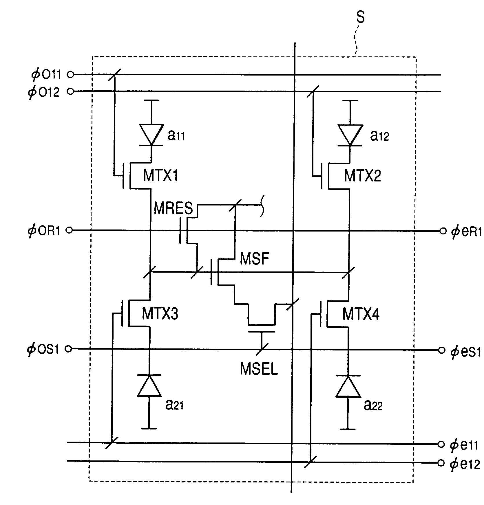
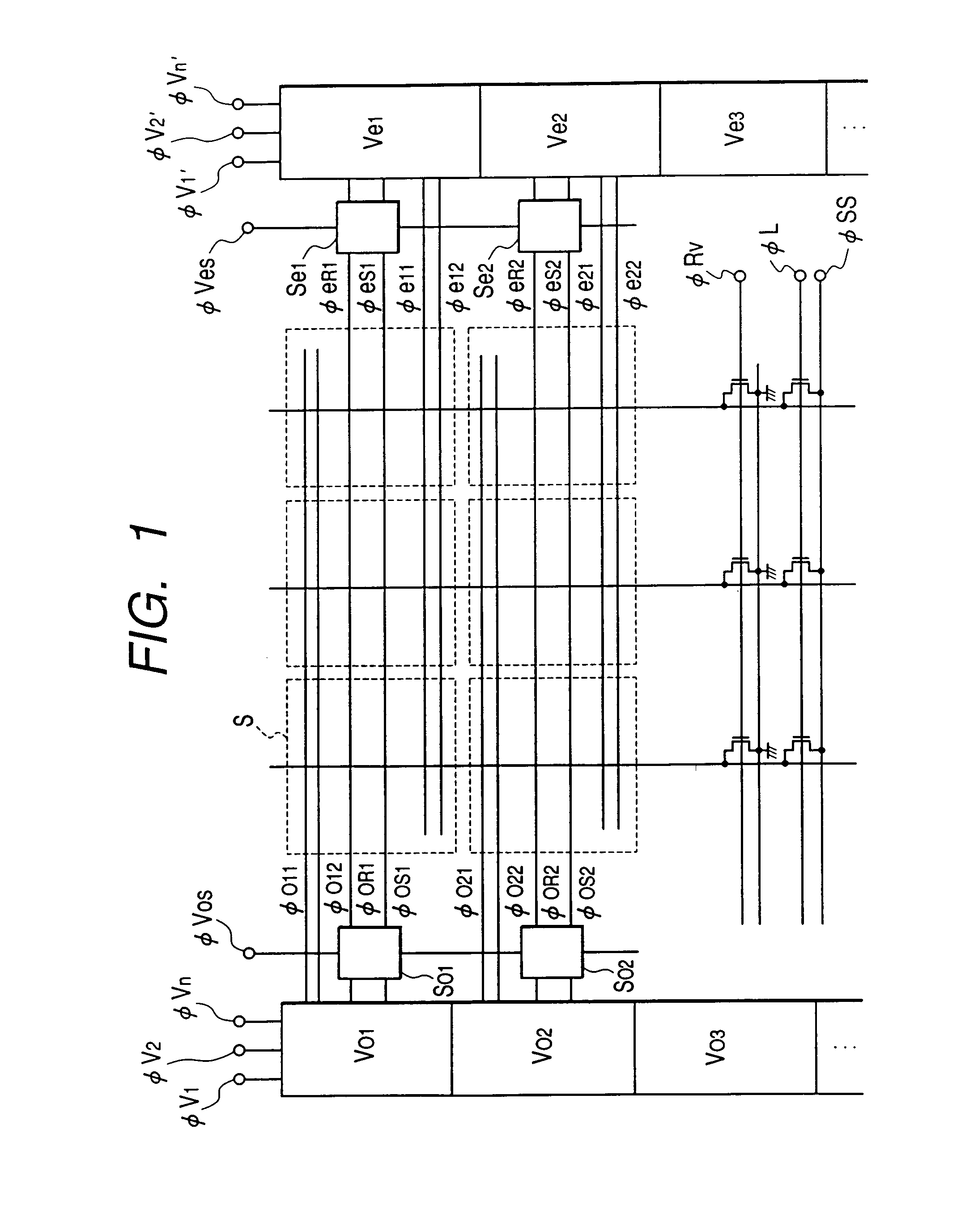
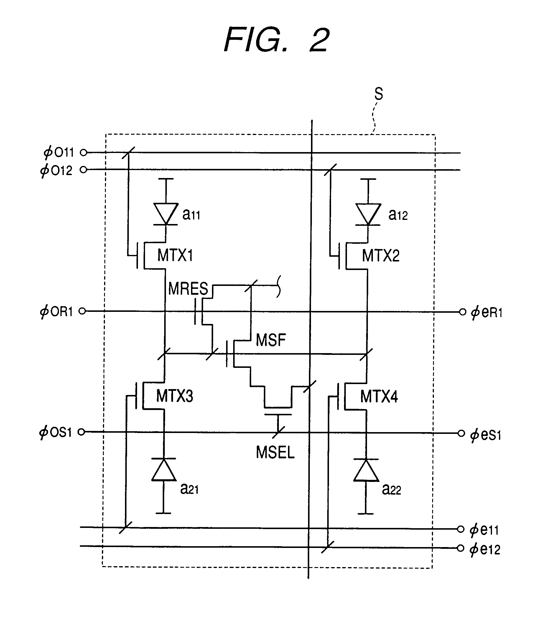
[0045]FIG. 1 is a schematic view showing the arrangement of part of an image pickup apparatus according to the present invention. FIG. 2 is a view showing the arrangement of a unit cell S of the image pickup apparatus shown in FIG. 1.
[0046]As shown in FIG. 2, the unit cell S is formed by arranging four photoelectric conversion portions (a11, a12, a21, and a22) for one common amplifier. The remaining unit cells have the same arrangement as that of the unit cell. The common amplifier comprises an amplification means MSF, reset means MRES, and select means MSEL. The input portion of the common amplifier corresponds to the gate portion of the amplification means MSF.
[0047]Lines for controlling signal transfer for two upper photoelectric conversion portions (a11 and a12) of the four pixels, that are adjacent to each other in the horizontal direction are connected to an odd vertical shift register Vo (Vo1, Vo2, Vo3 . . . ). Lines for controlling signal transfer for two lower photoelectric...
second embodiment
[0078]the present invention will be described next.
[0079]In this embodiment, an addition switching means for arbitrarily switching addition of signals from a plurality of photoelectric conversion portions at the input portion of a common amplifier is used to allow switching between various addition reading and full pixel reading as shown in Table 1.
[0080]FIG. 11 a schematic view showing a sensor so as to explain a sensor signal read mode.
[0081]This sensor has 1,300,000 effective pixels (∝1024V×1280H), and four photoelectric conversion portions (e.g., a11, a12, a21, and a22) for one common amplifier. This sensor can switch the read mode between A. full pixel independent read mode, B. vertical / horizontal four-pixel addition read mode, C. horizontal two-pixel addition read mode, and D. vertical two-pixel addition read mode shown in Table 1. This embodiment is not limited to a sensor having four photoelectric conversion portions per common amplifier and can also be applied to a sensor h...
third embodiment
[0124]the present invention will be described next.
[0125]In first embodiment signals from a plurality of photoelectric conversion portions in a unit cell and outside the unit cell can be added. In second embodiment, the mode can be switched between a mode for independently reading out signals from all photoelectric conversion portions of the unit cell, a mode for reading out a sum signal from four photoelectric conversion portions of the unit cell in the vertical and horizontal directions, a mode for reading out a sum signal from two, horizontally adjacent photoelectric conversion portions of the unit cell, and a mode for reading out a sum signal from two, vertically adjacent photoelectric conversion portions of the unit cell.
[0126]In this embodiment, the above four modes can be switched by combining the arrangements of the first and second embodiments. In addition, not only a sum signal from a plurality of photoelectric conversion portions in the unit cell but also a sum signal fro...
PUM
 Abstract
Description
Claims
Application Information