TLB lock and unlock operation

a technology of lock and unlock operation and translation lookaside buffer, which is applied in the field of computer processors, can solve the problems of different amount of processing time for different tasks

Inactive Publication Date: 2005-10-18
TEXAS INSTR INC
View PDF18 Cites 49 Cited by
  • Summary
  • Abstract
  • Description
  • Claims
  • Application Information

AI Technical Summary

Benefits of technology

[0016]In another embodiment, one or more TLB locations are reserved from being locked.
[0017]Another embodiment of the invention is a digital system that has a translation lookaside buffer (TLB). The TLB includes storage circuitry with a set of entry locations for holding translated values, wherein each of the set of entry locations includes a first field for a translated value and a second field for an associated qualifier value. There is a set of inputs for receiving a translation request, a set of outputs for providing a translated value selected from the set of entry locations; and control circuitry connected to the storage circuitry. The control circuitry is responsive to an operation command to lock or unlock selected ones of the set of entry locations that have a first qualifier value in the second field.
[0018]In another embodiment, the control circuitry includes a shift register connected to the storage circuitry for selecting a next victim entry location and skip circuitry connected to the shift register and to the storage circuitry. The skip circuitry is operable to cause the shift register to skip over locked entry locations.
[0019]In another embodiment, the control circuitry includes reservation circuitry operable to reserve a portion of the entry locations from being locked.

Problems solved by technology

Unfortunately, different tasks take different amounts of time to process.

Method used


Image

  • TLB lock and unlock operation
  • TLB lock and unlock operation
  • TLB lock and unlock operation

Examples


Embodiment Construction

[0033]Although the invention finds particular application to Digital Signal Processors (DSPs), implemented, for example, in an Application Specific Integrated Circuit (ASIC), it also finds application to other forms of processors. An ASIC may contain one or more megacells which each include custom designed functional circuits combined with pre-designed functional circuits provided by a design library.

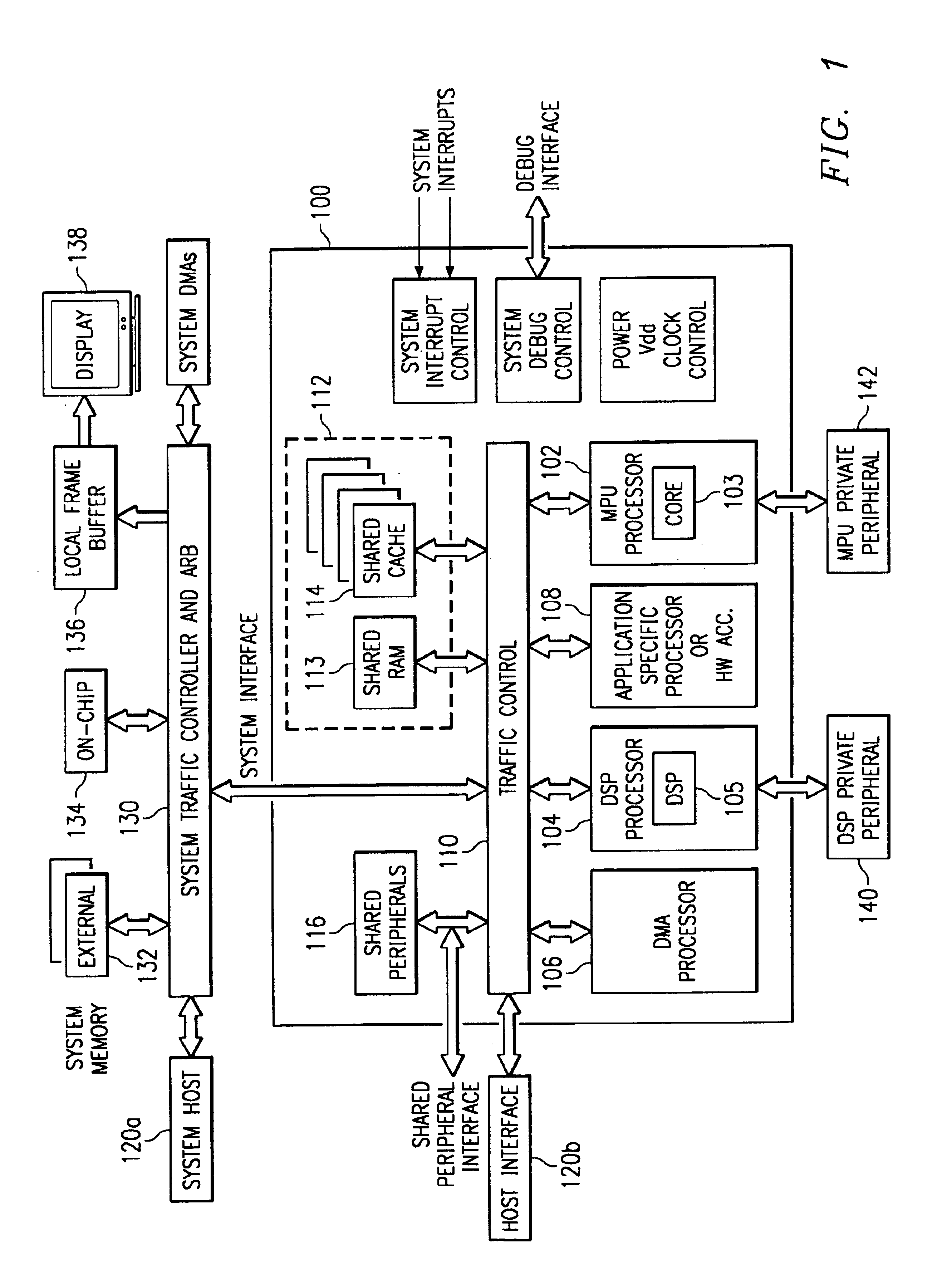
[0034]FIG. 1 is a block diagram of a digital system that includes an embodiment of the present invention in a megacell core 100 having multiple processor cores. In the interest of clarity, FIG. 1 only shows those portions of megacell 100 that are relevant to an understanding of an embodiment of the present invention. Details of general construction for DSPs are well known, and may be found readily elsewhere. For example, U.S. Pat. No. 5,072,418 issued to Frederick Boutaud, et al, describes a DSP in detail. U.S. Pat. No. 5,329,471 issued to Gary Swoboda, et al, describes in detail how to...


PUM


Abstract

A digital system and method of operation is provided in which several processing resources (340) and processors (350) are connected to a shared translation lookaside buffer (TLB) (300, 310(n)) of a memory management unit (MMU) and thereby access memory and devices. These resources can be instruction processors, coprocessors, DMA devices, etc. Each entry location in the TLB is filled during the normal course of action by a set of translated address entries (308, 309) along with qualifier fields (301, 302, 303) that are incorporated with each entry. Operations can be performed on the TLB that are qualified by the various qualifier fields. A command (360) is sent by an MMU manager to the control circuitry of the TLB (320) during the course of operation. Commands are sent as needed to flush (invalidate), lock or unlock selected entries within the TLB. Each entry in the TLB is accessed (362, 368) and the qualifier field specified by the operation command is evaluated (364). This can be task ID field 302, resource ID field 301, shared indicator 303, or combinations of these. Operation commands can also specify a selected virtual address entry (305). Each TLB entry is modified in response to the command (366) only if its qualifier field(s) match the qualifier(s) specified by the operation command.

Description

[0001]This application claims priority to European Application Serial No. 00402331.3, filed Aug. 21, 2000 (TI-31366EU) and to European Application Serial No. 01401216.5, filed May 11, 2001. U.S. patent application Ser. No. 09 / 932,651 is incorporated herein by reference.CO-RELATED APPLICATIONS[0002]This application is related to patent application Ser. No. 09 / 932,397 entitled TLB Operation Based on Task-ID; patent application Ser. No. 09 / 932,319, entitled TLB Operations Based on Shared Bit; and patent application Ser. No. 09 / 932,611, entitled TLB with Resource ID Field.FIELD OF THE INVENTION[0003]This invention generally relates to computer processors, and more specifically to improvements in translation lookaside buffers for address translation, systems, and methods of making.BACKGROUND[0004]Microprocessors are general purpose processors which provide high instruction throughputs in order to execute software running thereon, and can have a wide range of processing requirements depen...

Claims


Application Information

Patent Timeline
Patent Type & Authority Patents(United States)
IPC IPC(8): G06F1/32G06F1/20G06F12/12G06F11/34G06F12/08G06F12/02G06F12/10G06F9/312G06F12/0891G06F12/1027G06F12/1081G06F12/126
CPCG06F1/206G06F1/3203G06F1/329G06F9/30047G06F12/0891G06F12/1027G06F12/126Y02B60/1225G06F2201/81G06F2201/885G06F2212/1028G06F2212/681Y02B60/144G06F12/1081Y02D10/00
Inventor CHAUVEL, GERARD
Owner TEXAS INSTR INC
Why Eureka
Try Eureka