Combination utility and sporting knife

a technology of utility and sporting knives, applied in the field of cutting devices, can solve the problems of lack of versatility, inconvenient use for those who frequently use these devices, and lack of uniform handle orientation

Inactive Publication Date: 2005-10-25
STANLEY WORKS THE
View PDF58 Cites 49 Cited by
  • Summary
  • Abstract
  • Description
  • Claims
  • Application Information

AI Technical Summary

Problems solved by technology

However, this may become inconvenient to those who frequently use these devices.
The arrangement lacks a uniform handle orientation when using either the utility blade or the saw.
In addition, the saw is intended for a relatively specific purpose and lacks versatility.

Method used


Image

  • Combination utility and sporting knife
  • Combination utility and sporting knife
  • Combination utility and sporting knife

Examples


Embodiment Construction

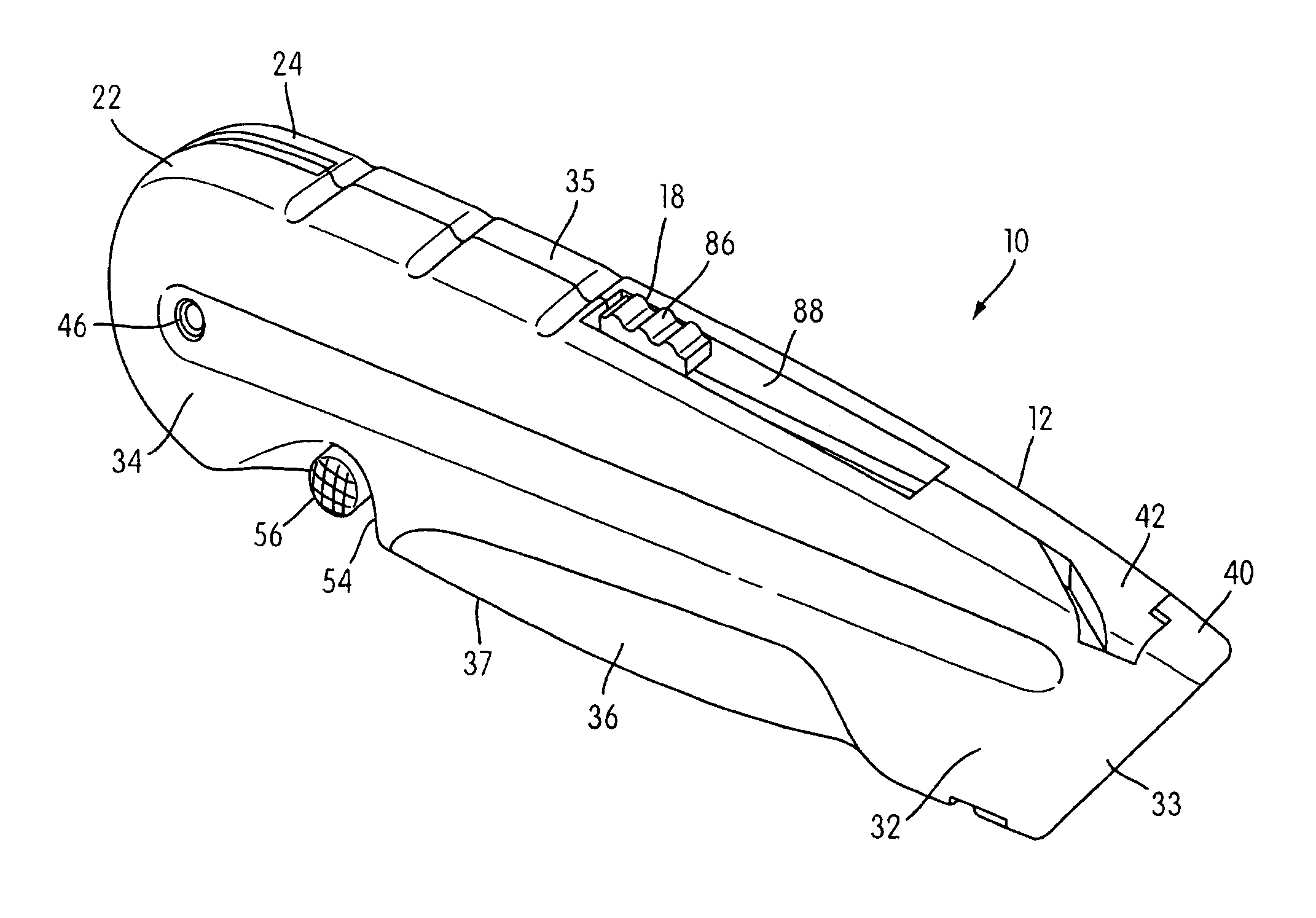
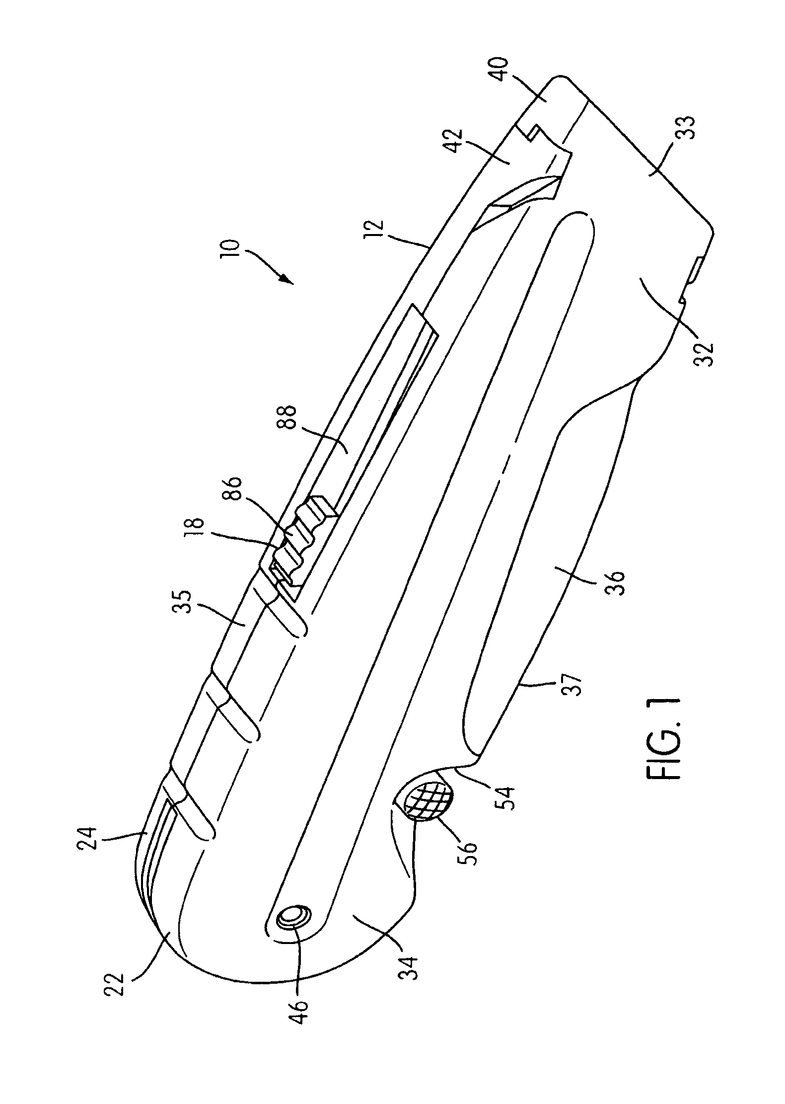
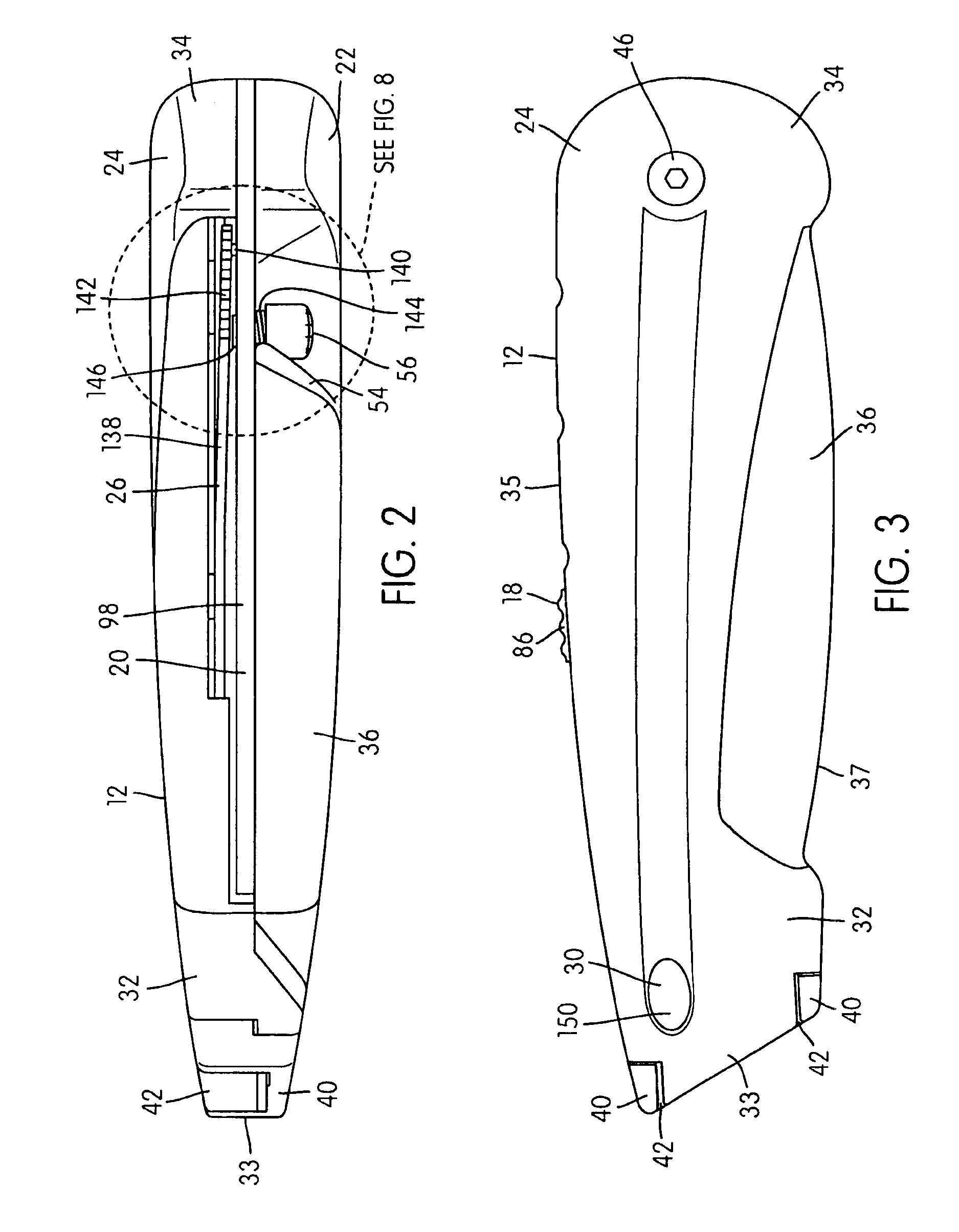
[0026]Referring now more particularly to the drawings, there is shown therein a combination utility and sporting knife 10 in accordance with one illustrated embodiment of the present invention. The main components of the combination 10 are a longitudinal knife handle 12, a utility blade carrier 14, a utility blade 16 carried by the blade carrier 14, a manual movable blade moving member 18 operatively connected with the blade carrier 14, and a pivotally movable blade 20. The utility blade carrier 14, the utility blade 16, and the manual movable blade moving member 18 may be referred to as a utility blade assembly 21.

[0027]As shown in FIGS. 1-4, the handle 12 is substantially hollow and includes first and second mating handle halves 22, 24 with the blade carrier 14 and the movable blade 20 movably mounted between the handle halves 22, 24. A movable blade locking mechanism 26, a blade interlocking mechanism 28, and a utility blade replacement mechanism 30 is also mounted between the ha...


PUM


Abstract

A combination utility and sporting knife includes a longitudinal knife handle, a utility blade carrier disposed within the handle and linearly movable within the handle, a utility blade carried by the blade carrier, a manual movable blade moving member operatively connected with the blade carrier, and a pivotally movable blade pivotally connected to the handle. The utility blade and the pivotally movable blade are extendable from opposite ends of the handle. The utility blade edge and the pivotally movable blade edge both are exposed towards the bottom portion of the handle when the pivotally movable blade and the utility blade are in operative positions thereof so that the bottom and top portions of the handle retain their relative bottom and top orientations for use of either the utility blade or the pivotally moveable blade.

Description

FIELD OF THE INVENTION[0001]The present invention relates generally to cutting devices.BACKGROUND OF THE INVENTION[0002]Cutting devices, such as utility blades and knives, are typically manufactured and used separately. However, this may become inconvenient to those who frequently use these devices.[0003]It has been proposed in U.S. Pat. No. 4,890,387 to provide a drywall utility knife that includes a utility blade at one end of the knife and a serrated drywall saw at the opposite end of the knife. As a result, the same utility knife may be conveniently used to both cut and saw drywall.[0004]However, this patent discloses an arrangement in which the cutting edge of the utility blade is exposed towards a bottom portion of the knife and the cutting edge of the saw is exposed towards an upper portion of the knife. The arrangement lacks a uniform handle orientation when using either the utility blade or the saw. In addition, the saw is intended for a relatively specific purpose and lack...

Claims


Application Information

Patent Timeline
Patent Type & Authority Patents(United States)
IPC IPC(8): B26B5/00B26B1/00B26B1/04
CPCB26B1/04B26B1/046B26B5/001
Inventor VAN DEURSEN, GARY E.ROWLAY, STEPHENROBERTS
Owner STANLEY WORKS THE
Why Eureka
Try Eureka