Closure mechanism with integrated actuator for subsurface valves

a technology of valve body and actuator, which is applied in the direction of valve body, sealing/packing, borehole/well accessories, etc., can solve the problem of doubt as to the available closure force of the flow tub

Inactive Publication Date: 2005-10-25
BAKER HUGHES INC
View PDF37 Cites 93 Cited by
  • Summary
  • Abstract
  • Description
  • Claims
  • Application Information

AI Technical Summary

Problems solved by technology

This concern also arose when there was sand, paraffin, asphaltine or other friction increasing compounds in the well fluids, creating doubt as to the available closure force on the flow tube from its power spring.

Method used


Image

  • Closure mechanism with integrated actuator for subsurface valves
  • Closure mechanism with integrated actuator for subsurface valves
  • Closure mechanism with integrated actuator for subsurface valves

Examples


Embodiment Construction

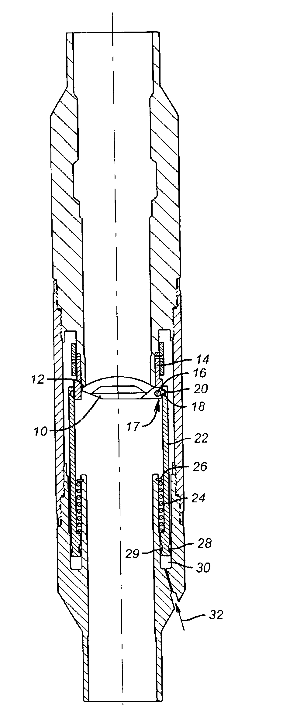
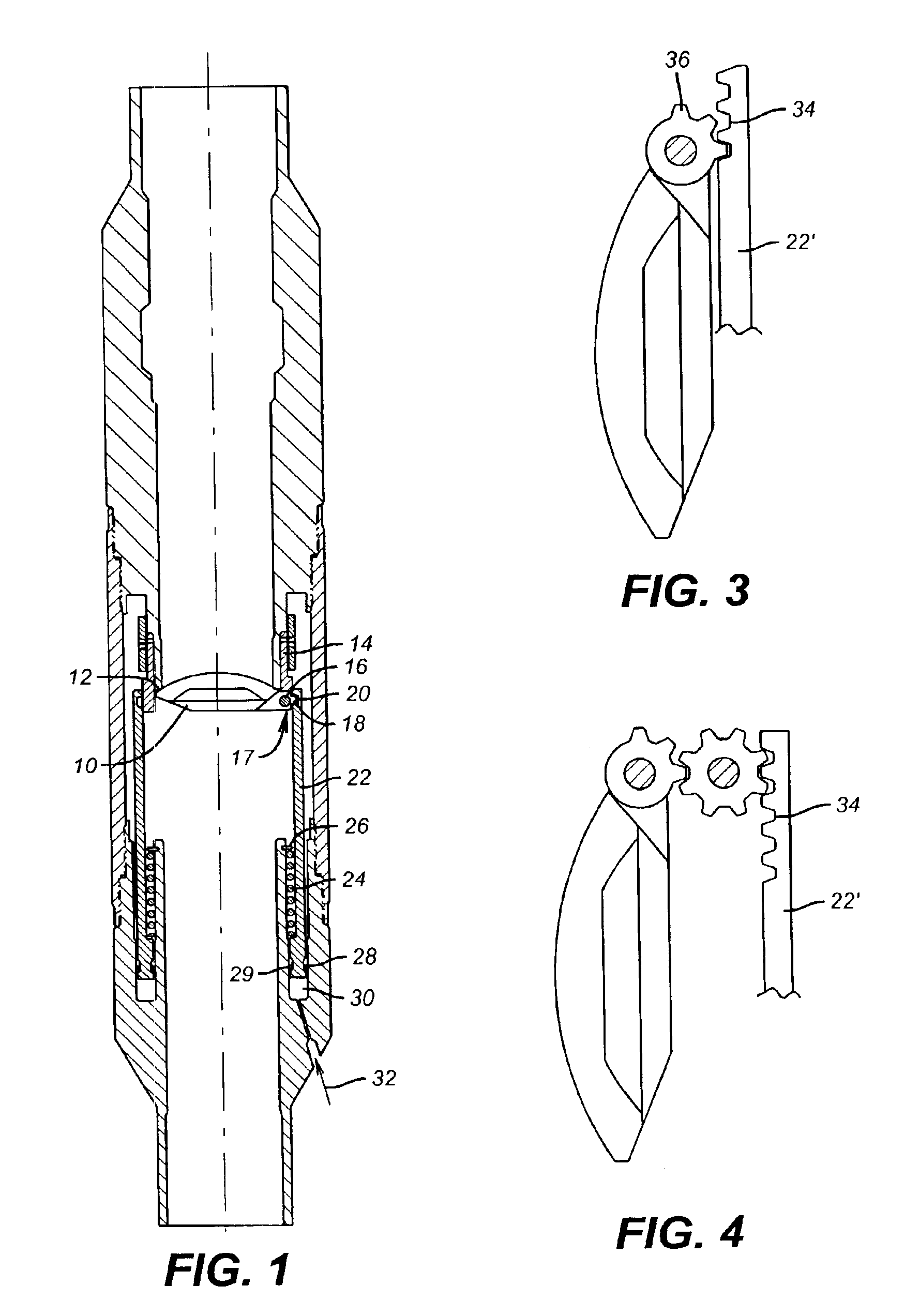
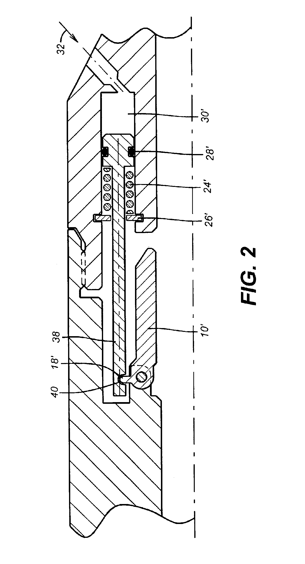
[0011]Referring to FIG. 1, the flapper 10 is shown in the closed position against a seat 12 located in body 14 of the SSV. The flapper 10 is connected to body 14 at pin 16 and hinge 17. Extending away from the sealing portion of the flapper 10 in contact with the seat 12 is an arm 18. Arm 18 extends into a groove 20 in annular piston 22. Spring 24 acting against stop 26 biases annular piston 22 downwardly. Seals 28 and 29 define a variable volume annular cavity 30. Arrow 32 shows schematically how the control line communicates hydraulic pressure (signal) from the well surface to overcome the downward bias of spring 24. Those skilled in the art will appreciate that the signal can be surface or downhole generated and can take various forms. The control system can involve electro-hydraulic (U.S. Pat. No. 6,269,874), electromechanical (U.S. Pat. No. 6,253,843), and photo-hydraulic techniques. When enough pressure is applied or some other signal is transmitted such as electromechanical, ...


PUM


Abstract

A subsurface safety valve has a closure sleeve or rod mounted below the closure mechanism. Control signal pushes the sleeve up (uphole) or down (downhole), whichever is applicable, which causes the closure element to rotate (or slide, or otherwise translate) to its open position. A loss of control signal allows the closure spring to push the sleeve or rod downhole (or uphole, whichever is appropriate). This movement causes the closure element to be driven to its closed position against the seat.

Description

PRIORITY INFORMATION[0001]This application claims the benefit of U.S. Provisional Application No. 60 / 334,321 filed on Nov. 30, 2001.FIELD OF THE INVENTION[0002]The field of this invention is surface controlled subsurface safety valves and more particularly actuating mechanisms for the closure element.BACKGROUND OF THE INVENTION[0003]Traditionally, sub-surface safety valves (SSSV) have had a flat or curved closure element known as a flapper, or a ball-shaped closure element, which rotates approximately 90 degrees, from opened to closed positions, under the bias of a closure spring generally mounted to the hinge holding the closure element to the valve body. The closure spring acts on the closure element after a flow tube or other actuating element is retracted. The flow tube and actuator mechanism are typically mounted above the closure element and inside the seat against which the closure element contacts for closure. The flow tube and actuator are biased in the uphole (closed) dire...

Claims


Application Information

Patent Timeline
Patent Type & Authority Patents(United States)
IPC IPC(8): E21B34/00E21B34/10
CPCE21B34/10E21B2034/005E21B2200/05
Inventor TROTT, DOUGLASSHAW, BRIANMCMAHON, DAVID
Owner BAKER HUGHES INC
Why Eureka
Try Eureka