Object location monitoring system

a technology for monitoring systems and objects, applied in the direction of direction finders using radio waves, testing/monitoring control systems, instruments, etc., can solve the problems of high degree of synchronization between the receivers, system is difficult and expensive to implement, and the location monitoring is not well suited for objects

Inactive Publication Date: 2005-10-25
GE MEDICAL SYST INFORMATION TECH
View PDF28 Cites 291 Cited by
  • Summary
  • Abstract
  • Description
  • Claims
  • Application Information

AI Technical Summary

Benefits of technology

[0008]The beacons and transponders are preferably assigned to timeslots of a TDMA frame so that nearby beacons and transponders do not interfere. In one embodiment, the beacons become synchronized with each other by monitoring the phase of the AC power signal on the building's power lines. This may be accomplished either directly or by monitoring the flicker of the building's lighting. Only coarse synchronization of the beacons is needed in comparison to prior approaches. The transponders preferably become synchronized to the beacons by monitoring a periodic synchronization sequence transmitted by one or more of the beacons.

Problems solved by technology

One problem with this approach is that it is not well suited for monitoring the locations of objects within a building having multiple rooms.
A significant problem with this approach is that a high degree of synchronization is required between the receivers to produce accurate results.
As a result, such a system tends to be difficult and expensive to implement.

Method used


Image

  • Object location monitoring system
  • Object location monitoring system
  • Object location monitoring system

Examples


Embodiment Construction

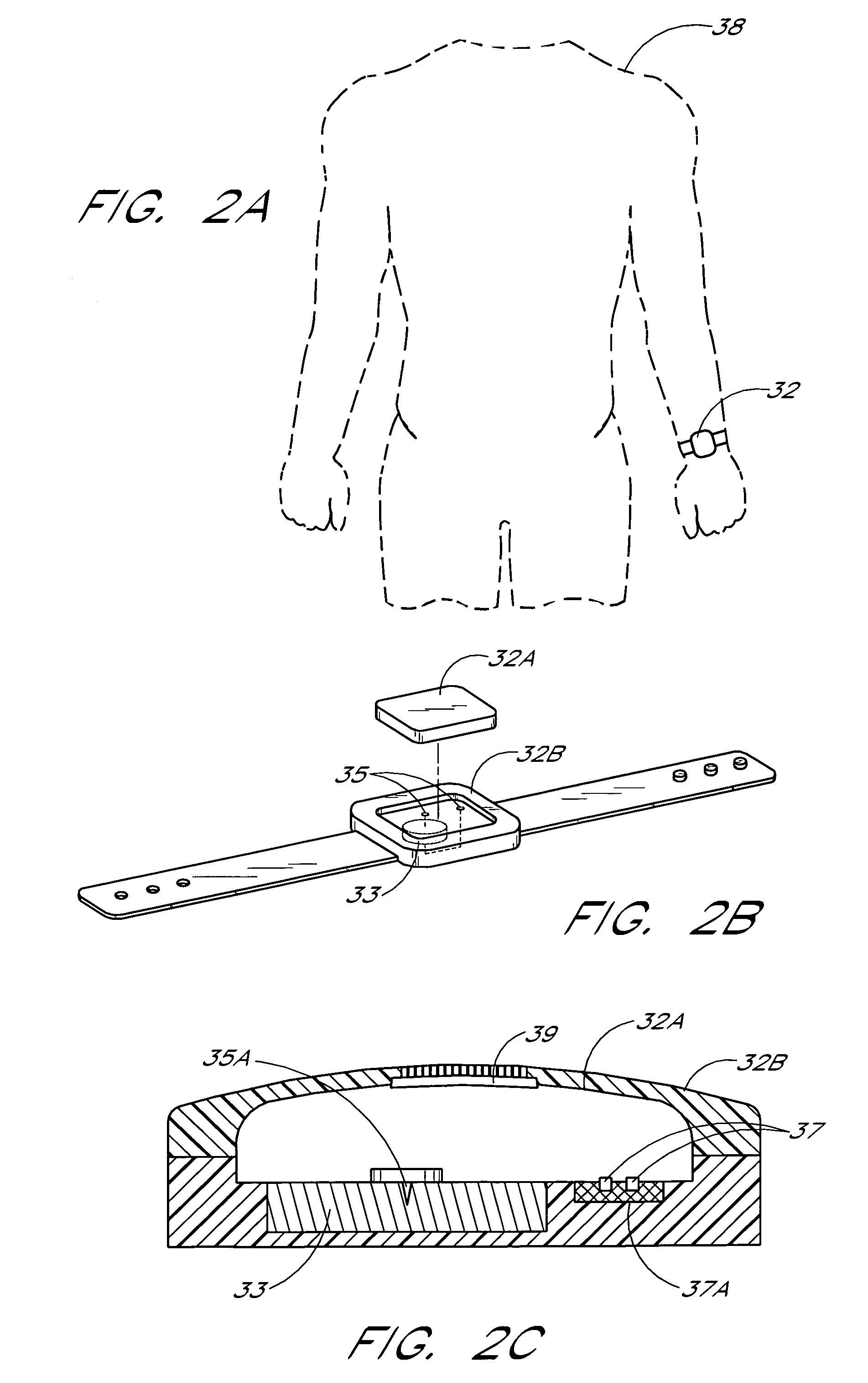
[0027]The specific embodiments described below are intended to illustrate, and not limit, the invention. The scope of the invention is defined by the appended claims. For convenience, the description of the preferred embodiments is arranged within the following sections:[0028]I. Overview (FIGS. 1 and 2A)[0029]II. Disposable Bracelet Transponder Design (FIGS. 2B and 2C)[0030]III. Waveform and Timing Diagrams (FIGS. 3–6)[0031]IV. Integration of Receivers with Network Access Points (FIG. 7)[0032]V. Example Beacon Circuit (FIGS. 8 and 9)[0033]VI. Example Transponder Circuit (FIG. 10)[0034]VII. Example Receiver Circuit (FIG. 11)[0035]VIII. Determination of Transponder Locations (FIG. 12)[0036]IX. Ultrasonic Embodiments[0037]X. Dithering of Beacon Timeslots to Avoid Lockstep Interference[0038]XI. Use of Building Power Lines to Convey Beacon Retransmissions

I. Overview (FIGS. 1 and 2A)

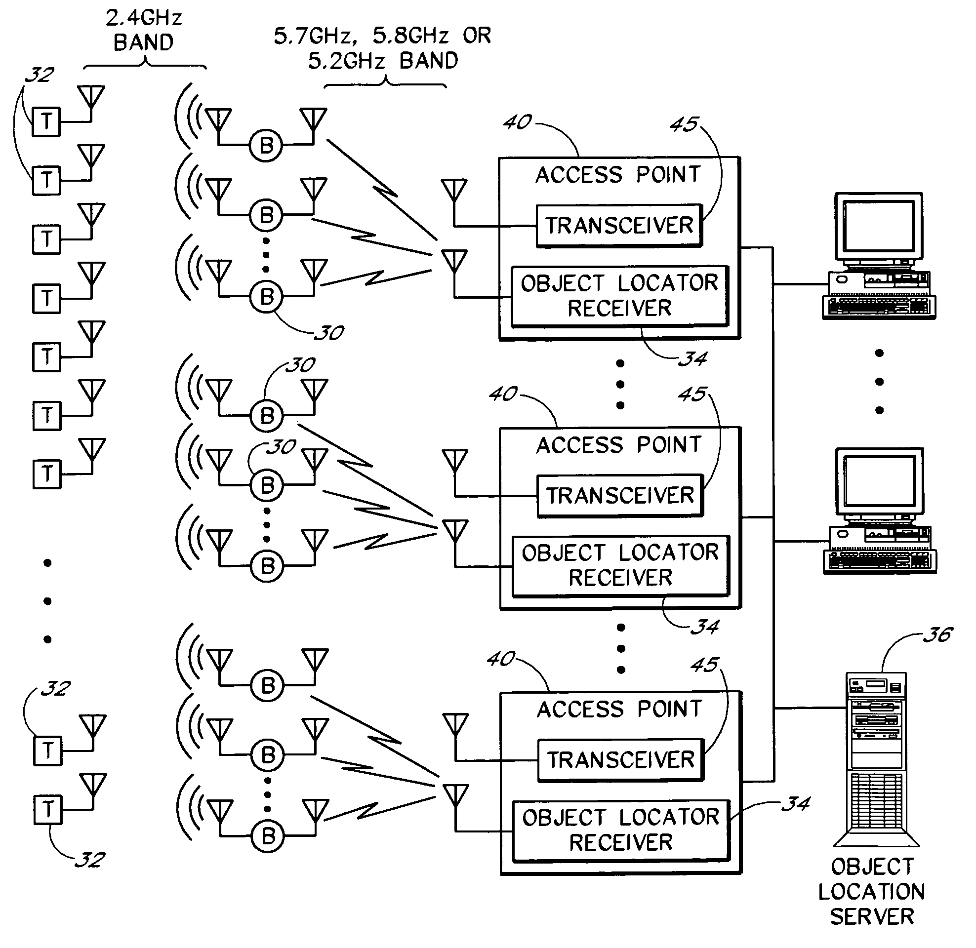
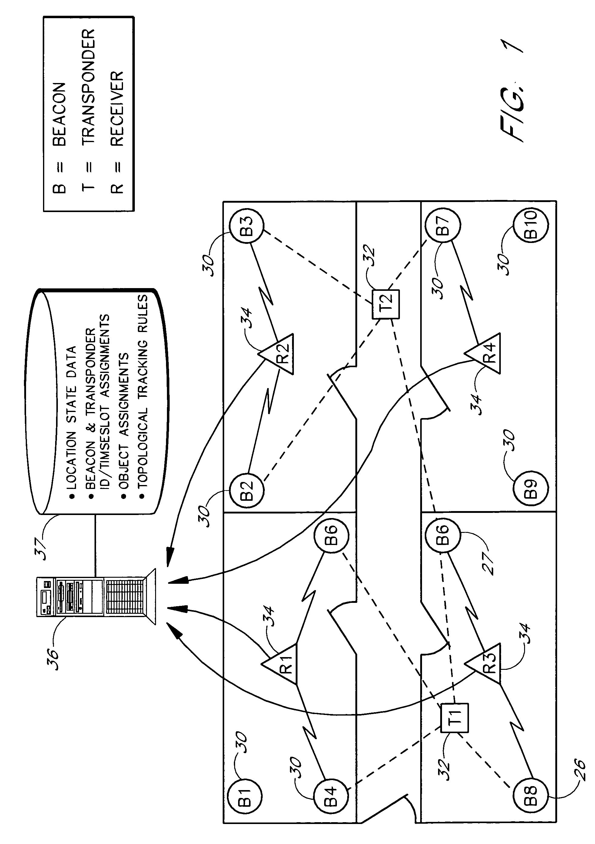
[0039]FIG. 1 illustrates the basic components of a real time object location tracking system according to o...


PUM


Abstract

An object location monitoring system includes beacons that are spatially distributed throughout an area to be monitored. The beacons transmit interrogation signals that are received and echoed by transponders that attach to moveable objects. Each beacon retransmits its interrogation signal, and any transponder response thereto, to a receiver that measures a time difference between the two signals. This time difference reflects the signal propagation time, and thus the distance, between the beacon and the transponder. One such receiver preferably analyzes the retransmitted signals of multiple (e.g., 50 to 100) beacons. A triangulation method is used to determine the location of each transponder based on the transponder's distances from a set of beacons. In one embodiment, the transponders are provided as or within disposable ID bracelets worn by patients, and are used to track the locations of the patients within a hospital.

Description

RELATED APPLICATIONS[0001]This application claims the benefit of Provisional Appl. No. 60 / 193,650, filed Mar. 31, 2000, the disclosure of which is hereby incorporated by reference.BACKGROUND[0002]1. Field of the Invention[0003]The present invention generally relates to object location monitoring systems for use in and around buildings. More specifically, the present invention relates to systems that use beacons and object-attached transponders to track the locations of objects.[0004]2. Description of the Related Art[0005]Various approaches have been proposed for monitoring the locations of objects within an area. One such approach uses radio frequency (RF) transmitters or tags, attached to the objects to be tracked, and an array of receivers for receiving tag transmissions throughout a tracking area. The signal strengths of the received tag transmissions may then be used to determine a tag's distance from the receivers. One problem with this approach is that it is not well suited fo...

Claims


Application Information

Patent Timeline
Patent Type & Authority Patents(United States)
IPC IPC(8): H04Q5/00H04Q5/22G06K17/00
CPCG06K17/00G06K19/07762G06K2017/0045
Inventor CARTER, SCOTT J.
Owner GE MEDICAL SYST INFORMATION TECH
Why Eureka
Try Eureka