Fixing device and image forming apparatus

a technology of fixing device and image forming apparatus, which is applied in the direction of electrographic process, electric/magnetic/electromagnetic heating, instruments, etc., can solve the problems of insufficient safety of conventional software, and achieve the effect of high-quality image formation and enhanced temperature abnormality detection accuracy of induction heating apparatus

Inactive Publication Date: 2005-10-25
CANON KK
View PDF6 Cites 20 Cited by
  • Summary
  • Abstract
  • Description
  • Claims
  • Application Information

AI Technical Summary

Benefits of technology

[0005]Accordingly, it is a principal object of the present invention to provide a fixing device wherein the temperature abnormality detection accuracy of induction heating apparatus is enhanced, and an image forming apparatus capable of high quality image formation.

Problems solved by technology

However, when the fixing roller is rapidly heated as with the said induction heating type, the conventional software safety means is insufficient.
The temperature rise of the heating member can be so quick that temperature of the heating member may rise to such a temperature as to cause a mechanical malfunction before the actuation of the hardware temperature detecting means using a mechanical contact for the excessive temperature rise detection, is actuated.

Method used


Image

  • Fixing device and image forming apparatus
  • Fixing device and image forming apparatus
  • Fixing device and image forming apparatus

Examples


embodiment 1

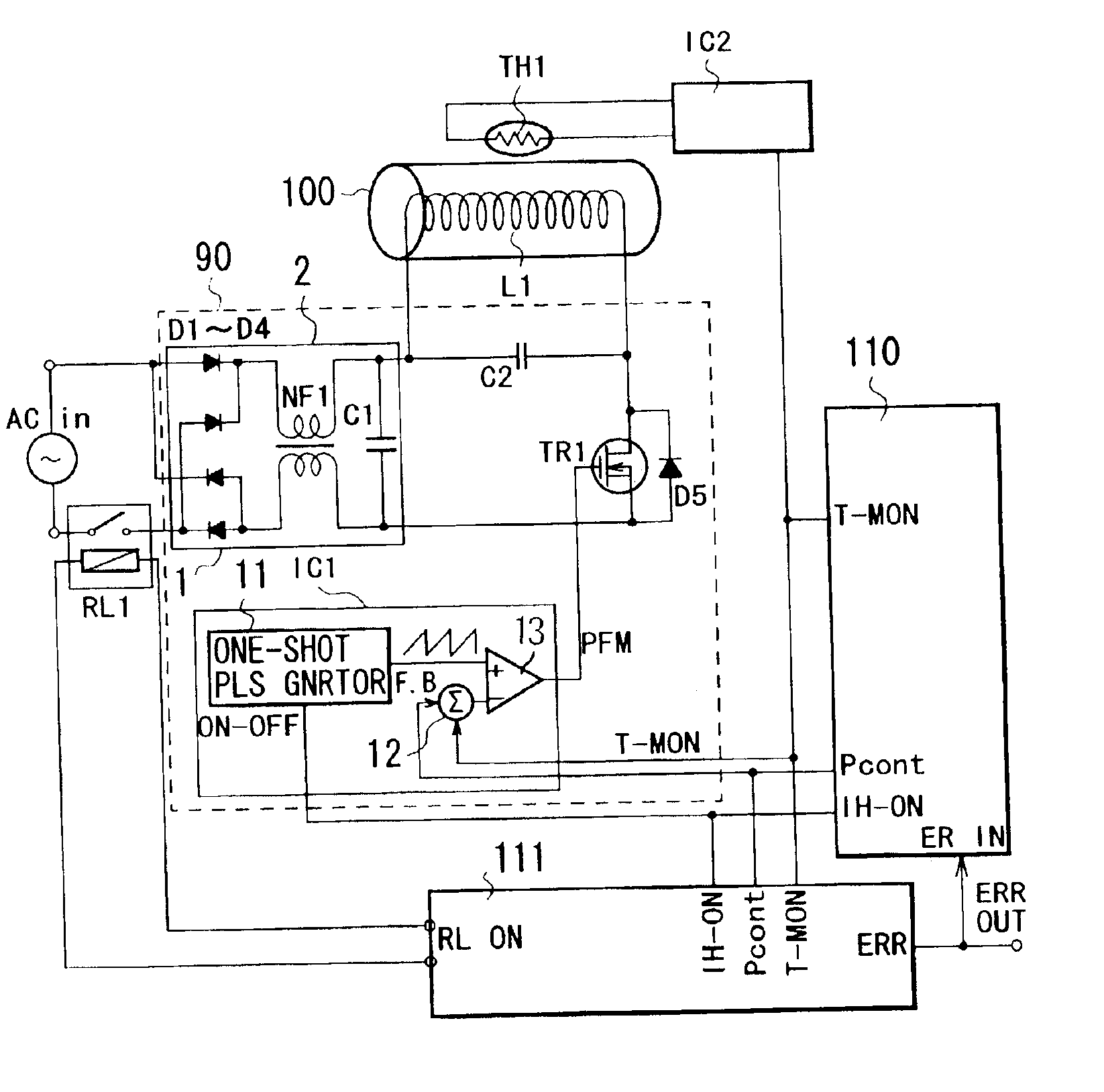
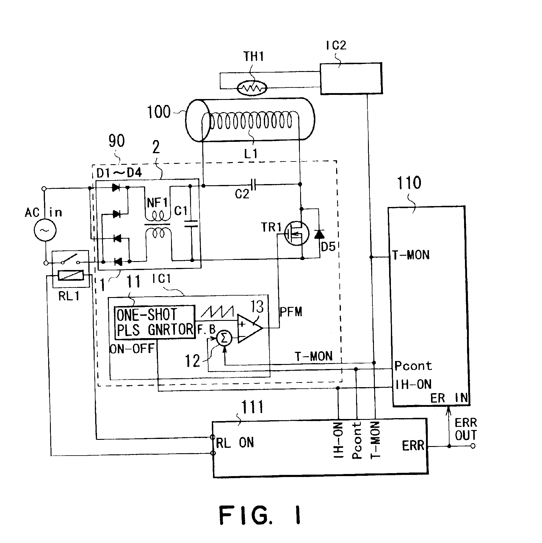
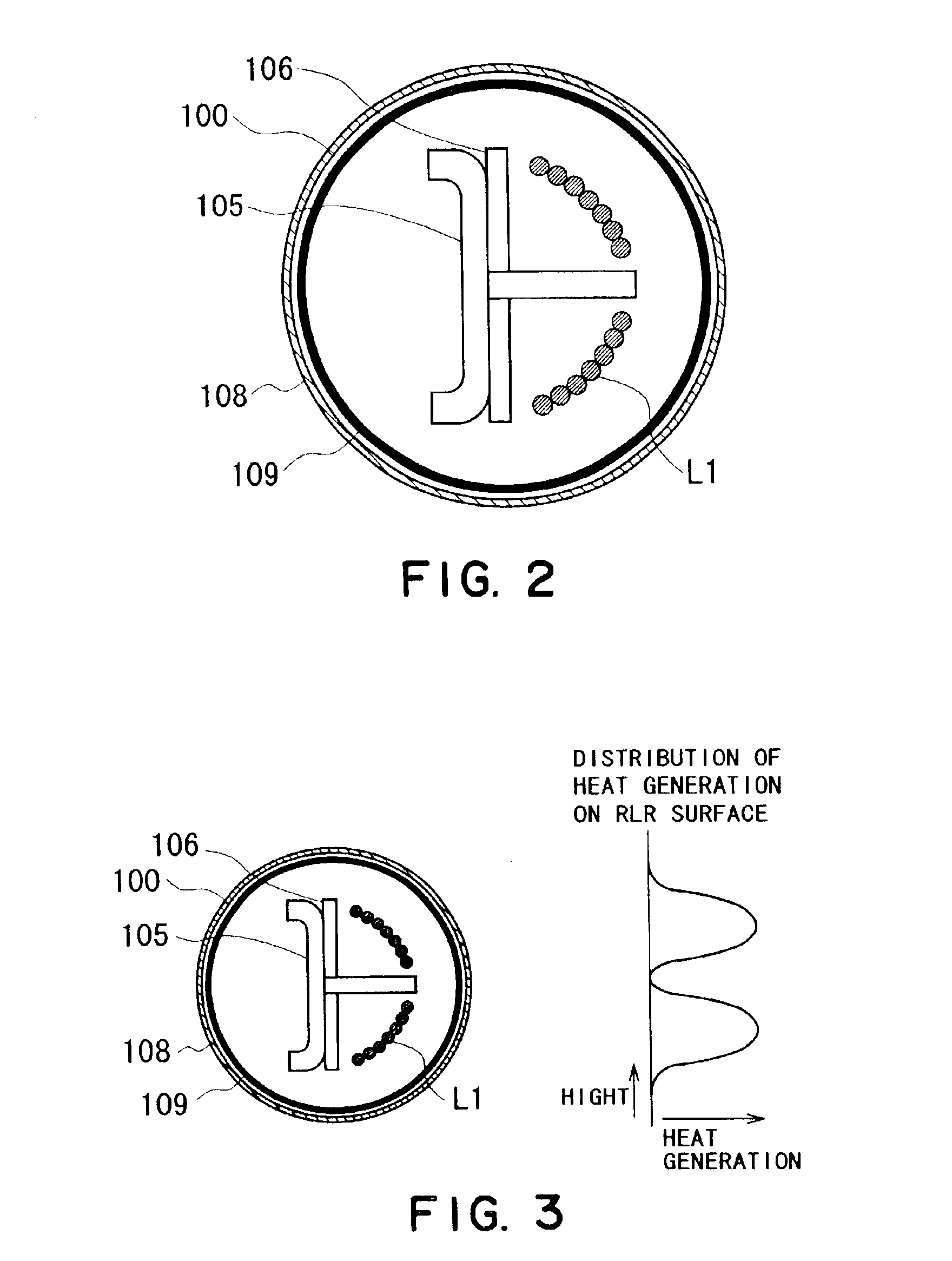
[0022]FIG. 1 is a schematic block diagram of an induction heating apparatus in Embodiment 1 of the present invention. FIG. 2 is a detailed illustration of an inside structure of the fixing roller. FIG. 3 is an illustration of a heat generation distribution of the fixing roller. FIG. 4 is an illustration of a normal sequence profile upon temperature raising. FIG. 5 is an illustration of an abnormality sequence profile upon temperature raising. FIG. 6 is a schematic block diagram of an induction heating apparatus in Embodiment 1 of the present invention. FIG. 7 is an illustration of abnormality discrimination on the basis of temperature information wherein a temperature reference profile is produced by an electric power control circuit. FIG. 8 shows an induction heating apparatus in the form of a fixing device. FIG. 9 illustrates an induction heating apparatus in the form of an image forming apparatus. In these Figures, the same reference numerals are assigned to the elements having c...

embodiment 2

[0059]FIG. 6 is a schematic block diagram of the device and method in another embodiment of the present invention. In this embodiment, the electric power control circuit 110 is given the function of keeping and outputting in time series the temperature rising level in the case of normal operation (reference). Simultaneously with outputting the operation permission signal IH-ON and the electric power instruction value Pcont, the normal temperature rising output level is supplied to the abnormality detecting circuit 111 as a temperature reference signal T-Ref.

[0060]In the abnormality detecting circuit 111, the abnormality detection level is set on the basis of the temperature reference signal TRef supplied from the electric power control circuit 110. For example, as shown in FIG. 7, the high temperature abnormality detection level THL is determined as 1.2 times the temperature reference signal T-Ref, and the low temperature abnormality detection level TLL is determined as 0.8 times th...


PUM


Abstract

A fixing device has a magnetic field generator; an electric power supplier for electric power supply to the magnetic field generator; electric power controller for controlling an electric power value to be supplied by the electric power supplier; a fixing member, disposed in the magnetic field, having an electroconductive layer which generates heat by eddy current generated by the magnetic field; a temperature detecting member for detecting a temperature of the fixing member; a discriminator for discriminating whether the apparatus is in order by comparing a detected temperature to a reference temperature in a period from a start of heating the fixing member to arrival at a predetermined temperature; and a reference temperature changer for changing the reference temperature on the basis of the supplied electric power value upon the electric power controller changing the electric power value.

Description

FIELD OF THE INVENTION AND RELATED ART[0001]The present invention relates to a fixing device for heating and fixing of a recording paper (recording material) with heat-fusing powder such as toner using induction heating as a heat generation source. An image forming apparatus comprises image forming means for forming a visualized image (toner image) on a recording material (recording paper) with visualizing material (toner), recording paper feeding means for feeding recording paper on which the toner image is formed and fixing means for heating and fixing the toner image on the recording paper.[0002]Recently, an induction heating type comprising a fixing roller (heating member) 100 and a pressing roller 101 which are press-contacted to each other as shown in FIG. 8 is noted from the standpoint of saving energy consumption. In the induction heating type, the high frequency current is applied to the induction heating coil L1, the generated high frequency magnetic field acts on the elec...

Claims


Application Information

Patent Timeline
Patent Type & Authority Patents(United States)
IPC IPC(8): G03G15/20
CPCG03G15/20G03G15/2039
Inventor OHTA, TOMOICHIROU
Owner CANON KK
Why Eureka
Try Eureka