Sheet metal bending brake

a technology of bending brakes and bending plates, which is applied in the direction of vices, clamps, manufacturing tools, etc., can solve the problems of insufficient friction engagement of the cams with their circular openings in the pivot arms

Inactive Publication Date: 2005-11-01
BREAK DOUGLAS G
View PDF8 Cites 5 Cited by
  • Summary
  • Abstract
  • Description
  • Claims
  • Application Information

AI Technical Summary

Benefits of technology

[0020]A link is rotatably mounted at one end to each cam along a first axis eccentric to the axis of rotation of the cam while the opposite end of each link is pivotally connected to each pivot arm. A shaft is then drivingly attached to each cam about the first axis so that rotation of the shaft by a handle vertically displaces the links and thus vertically displaces the pivot arms. The trapezoidal opening in the frame members, however, ensures that the cam maintains clamping frictional contact with both sides of the trapezoidal opening regardless of the degree of opening of the bending brake thereby achieving secure clamping for work pieces of a wide range of thicknesses.

Problems solved by technology

When this happens, the frictional engagement of the cams with their circular openings in the pivot arms is insufficient to frictionally lock the cams against rotation to the pivot arms.

Method used


Image

  • Sheet metal bending brake
  • Sheet metal bending brake
  • Sheet metal bending brake

Examples


Embodiment Construction

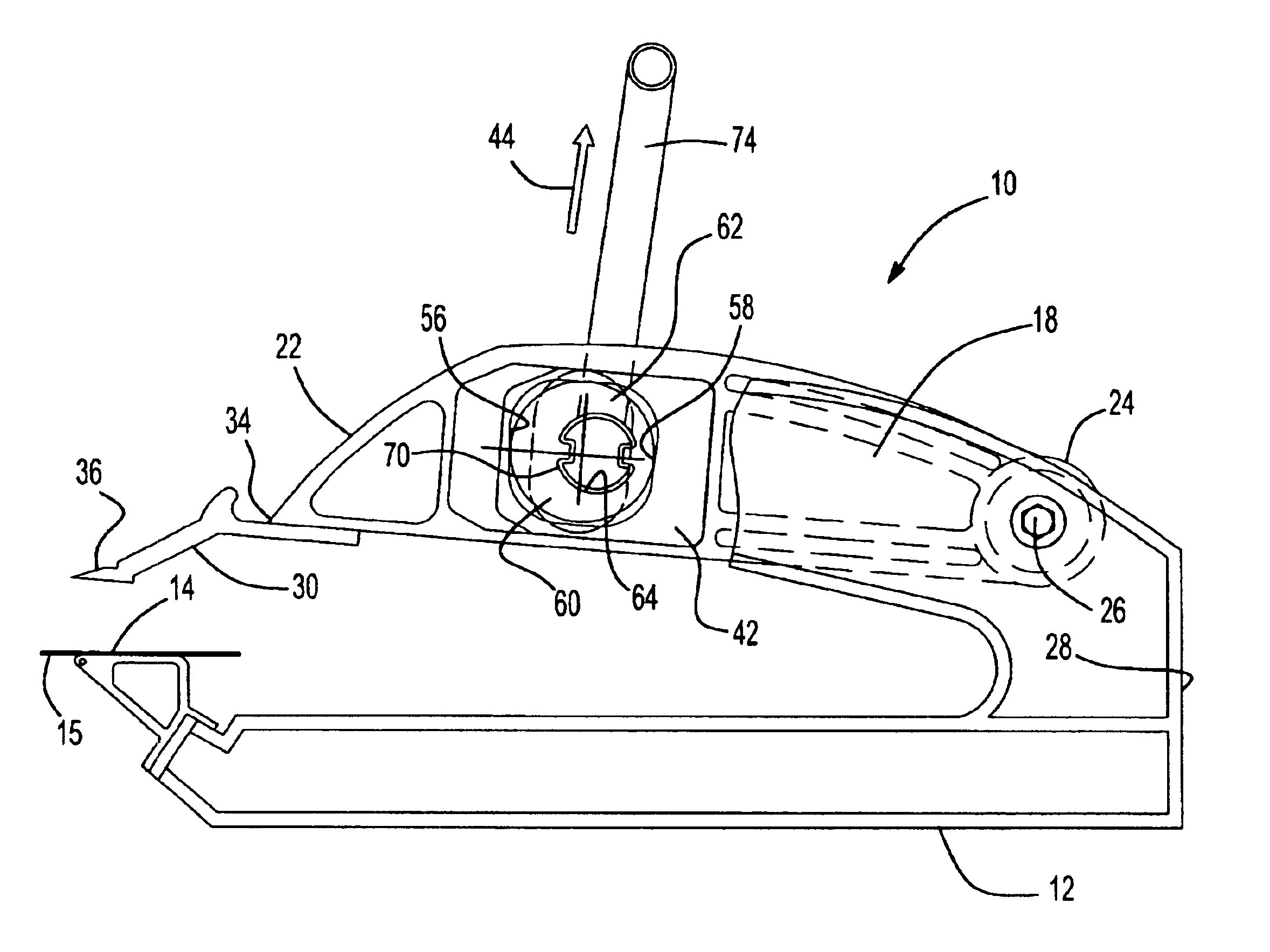
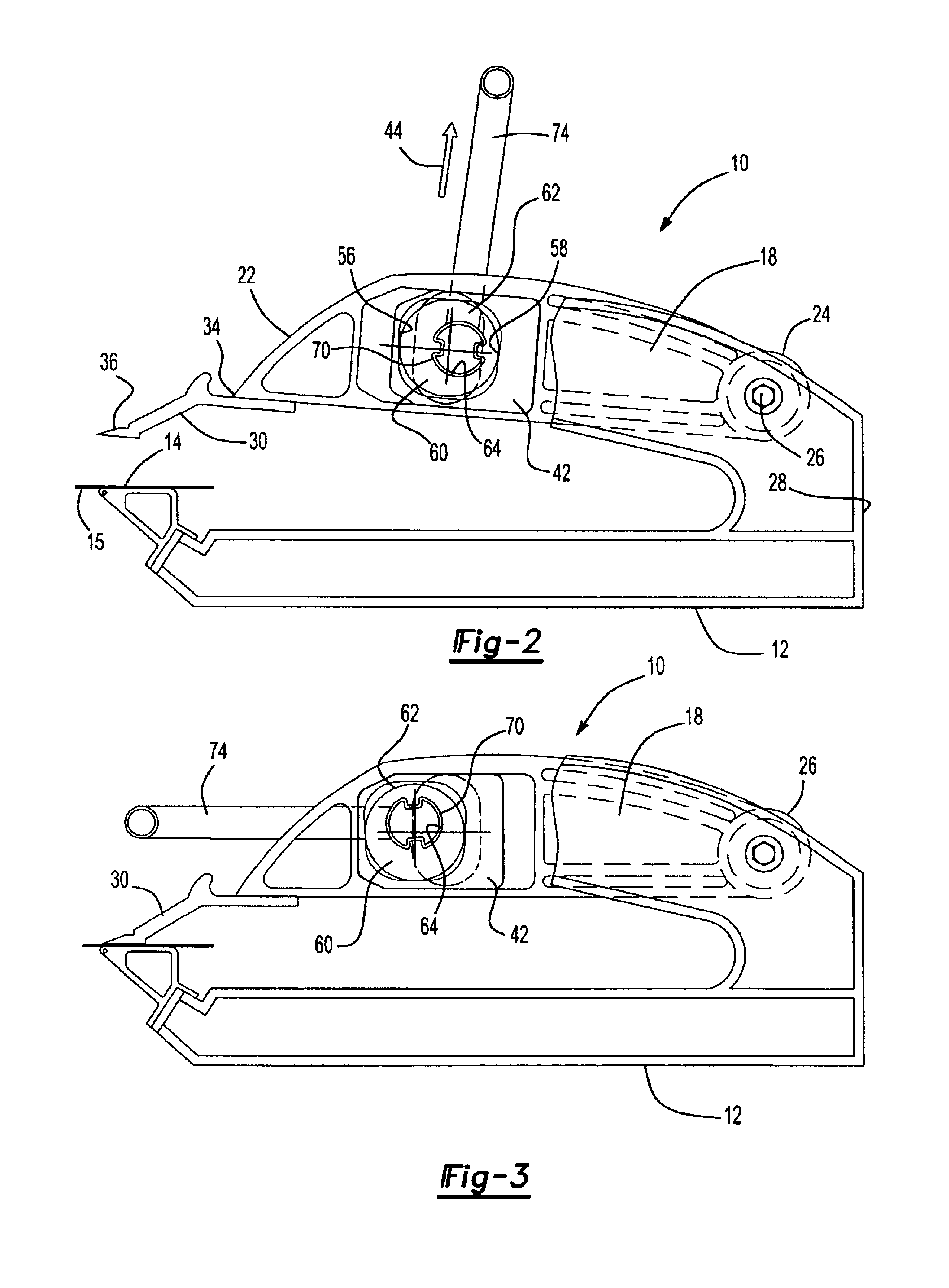
[0029]With reference first to FIGS. 1 and 2, a first preferred embodiment of the sheet metal bending brake 10 is shown having a frame 12 constructed of any rigid material, such as aluminum. The frame 12 defines an elongated and generally planar work support surface 14 (FIG. 2) extending along a front 16 of the bending brake 10 adapted to support a workpiece 15, such as a piece of sheet metal.

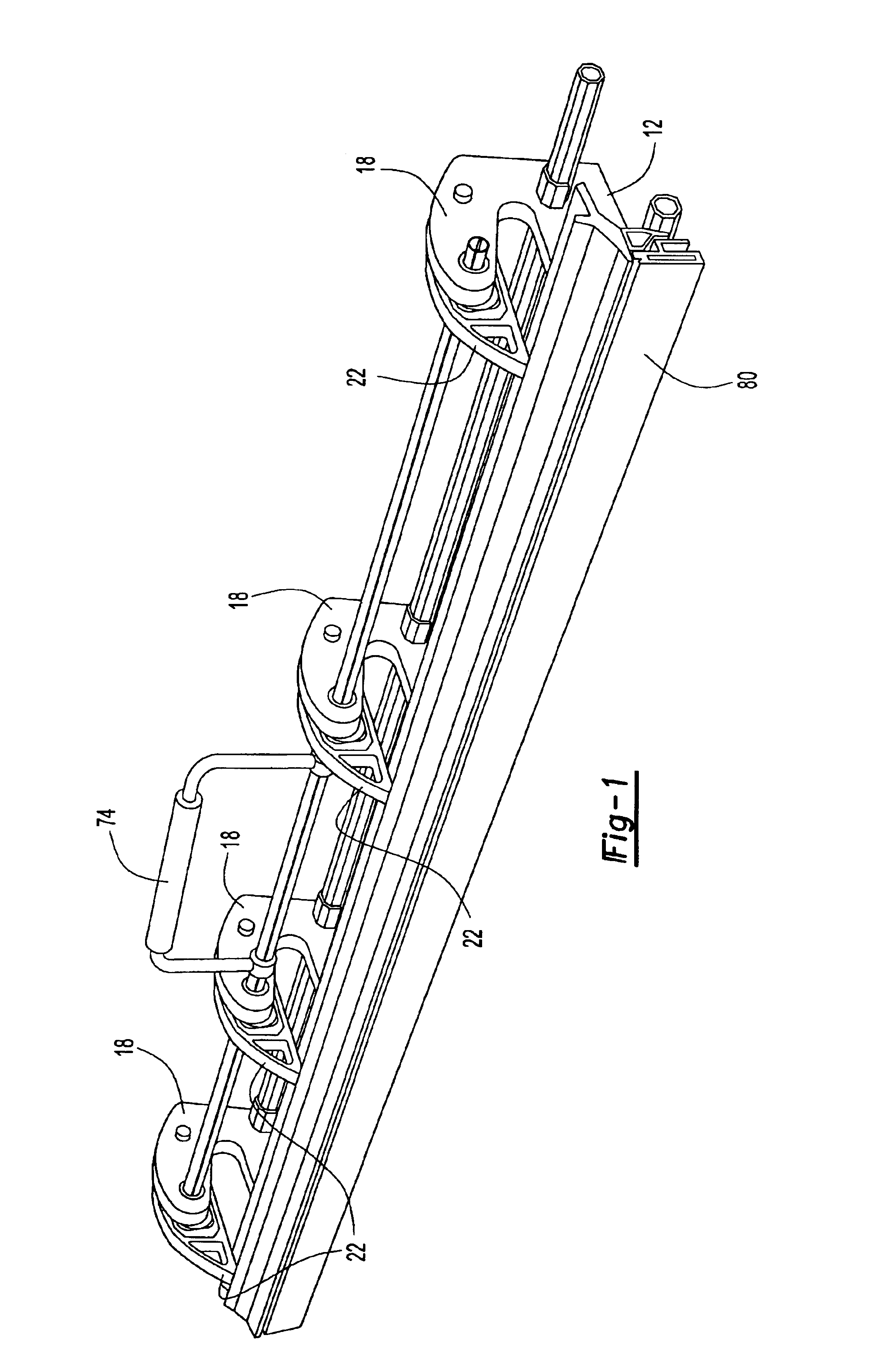
[0030]As best shown in FIGS. 1 and 4, the frame 12 further includes a plurality of laterally spaced apart frame members 18 which extend above the work support surface 14. Each frame member 18, furthermore, includes a throughbore 20 such that the throughbores 20 of the frame members 18 are aligned and coaxial with each other.

[0031]With reference now particularly to FIGS. 2-4, a plurality of elongated pivot arms 22 each have one end 24 pivotally secured by a pin 26 (FIG. 2) to the frame 12 adjacent its rear side 28. An elongated clamp bar 30 is then secured by any conventional means to a front end...


PUM

PropertyMeasurementUnit
movementaaaaaaaaaa
thicknessaaaaaaaaaa
rotational movementaaaaaaaaaa

Abstract

A sheet metal bending brake having a frame with a planar work supporting surface and a plurality of spaced frame members extending over the work support surface. Each frame member has a throughbore and these throughbores are aligned with each other. A plurality of elongated pivot arms are pivotally secured at one end to the frame for movement toward and away from the work supporting surface. Each pivot arm also includes a generally rectangular opening aligned with the frame member throughbores. A block is longitudinally slidably mounted in each pivot arm opening and this slide block is constrained against movement in a direction perpendicular to the work support surface. Each block furthermore includes a trapezoidal opening with spaced apart and parallel top and bottom surfaces and outwardly flared side surfaces. An elongated shaft extends through and is rotatably mounted to the frame member throughbores and this shaft also extends through the trapezoidal openings in the pivot arms. A plurality of eccentric cams are secured to the shaft so that one cam is associated with and positioned within each trapezoidal opening. This cam is dimensioned so that the cam contacts the outwardly flared side surfaces of its associated slide block regardless of the rotational position. Pivotal movement of the shaft thus displaces the pivot arms in a direction generally perpendicular to the work support surface due to the coaction of the eccentric cams with the side surfaces of the slide blocks.

Description

RELATED APPLICATION[0001]This application claims priority of U.S. Provisional Patent Application Ser. No. 60 / 414,907 filed Sep. 30, 2002, which is incorporated herein by reference.BACKGROUND OF THE INVENTION[0002]I. Field of the Invention[0003]The present invention relates to sheet metal bending brakes.[0004]II. Description of Related Art[0005]There are many previously known portable sheet metal bending brakes that are used in the building construction industry, typically for the installation of aluminum siding. These previously known sheet metal bending brakes typically comprise a frame having a planar work support surface and a plurality of spaced frame members which extend over the work support surface. Each frame member, furthermore, includes a throughbore so that the throughbores in the frame members are aligned with each other.[0006]A plurality of elongated pivot arms are pivotally secured at one end to the frame for movement at their opposite ends toward and away from the wor...

Claims


Application Information

Patent Timeline
Patent Type & Authority Patents(United States)
IPC IPC(8): B21D5/04
CPCB21D5/04
Inventor BREAK, DOUGLAS G.
Owner BREAK DOUGLAS G
Why Eureka
Try Eureka