Threading apparatus for sewing machine

a technology for sewing machines and thread holding members, applied in sewing apparatuses, needle bars, textiles and paper, etc., can solve the problem of only tight threading before, and achieve the effect of reliably catching thread holding, reducing the moving speed of thread holding members, and passing through needle eye reliably

Inactive Publication Date: 2005-11-01
BROTHER KOGYO KK
View PDF7 Cites 10 Cited by
  • Summary
  • Abstract
  • Description
  • Claims
  • Application Information

AI Technical Summary

Benefits of technology

[0006]Therefore, an object of the present invention is to provide a sewing machine in which the thread can reliably be passed through the needle eye.
[0007]The present invention provides a sewing machine comprising a sewing needle having an eye, a threading hook passed through the eye of the needle, a traveling mechanism for traveling the threading hook so that the threading hook is advanced through the eye of the needle and retreated through the eye of the needle, a thread holding member for holding the thread, a moving mechanism for moving that the thread holding member between a first position where the thread holding member is close to the threading hook having been advanced through the eye of the needle and a second position where the thread holding member is away from the threading hook having been advanced through the eye of the needle, and a speed reducing mechanism for reducing a moving speed of the thread holding member while the thread holding member is holding the thread and being moved near the threading hook having been advanced through the eye of the needle.
[0008]In the foregoing sewing machine, the thread holding member is moved slowly near the threading hook having been passed through the eye of the needle. Consequently, the threading hook can reliably catch the thread held by the thread holding member.
[0009]In a preferred form, the sewing machine further comprises a hook holding member for holding the threading hook, and the speed reducing mechanism abuts the hook holding member on the thread holding member, thereby reducing the moving speed of the thread holding member. In this case, since this construction requires no members dedicated to speed reduction of the thread holding member or no control mechanism, the construction of the speed reducing mechanism can be simplified.
[0010]The invention also provides a sewing machine comprising a sewing needle having an eye, a threading hook passed through the eye of the needle, a traveling mechanism for traveling the threading hook so that the threading hook is advanced through the eye of the needle and retreated through the eye of the needle, a thread holding member including a thread holding portion for holding a thread in a stretched state, and a moving mechanism for moving the thread holding member so that the thread held by the thread holding portion intersects a portion of the threading hook protruding from the eye of the needle, the threading hook having been advanced through the eye of the needle. In this construction, too, the thread held by the thread holding member can reliably be caught by the threading hook and passed through the eye of the needle.
[0011]The thread holding member preferably has a plurality of thread holding portions spaced apart from each other, and the moving mechanism preferably moves the thread holding member so that said protruding portion of the needle eye passes between the thread holding portions. In this construction, the thread held by the thread holding portion can reliably be caused to intersect the threading hook having been passed through the eye of the needle.

Problems solved by technology

Furthermore, although the thread is caused to come close to the needle eye in the above-described threading apparatus, the thread is only tight-stretched before the needle eye.

Method used


Image

  • Threading apparatus for sewing machine
  • Threading apparatus for sewing machine
  • Threading apparatus for sewing machine

Examples


Embodiment Construction

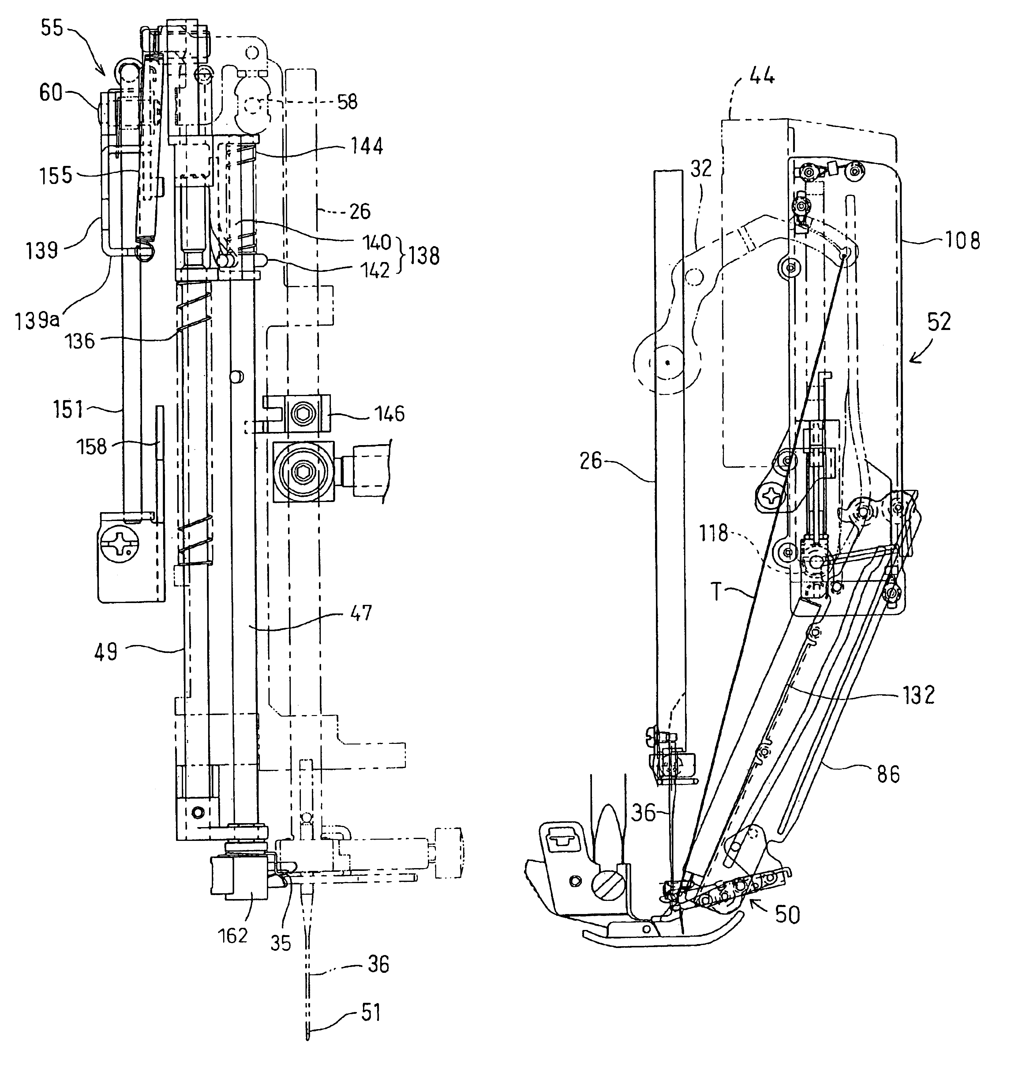
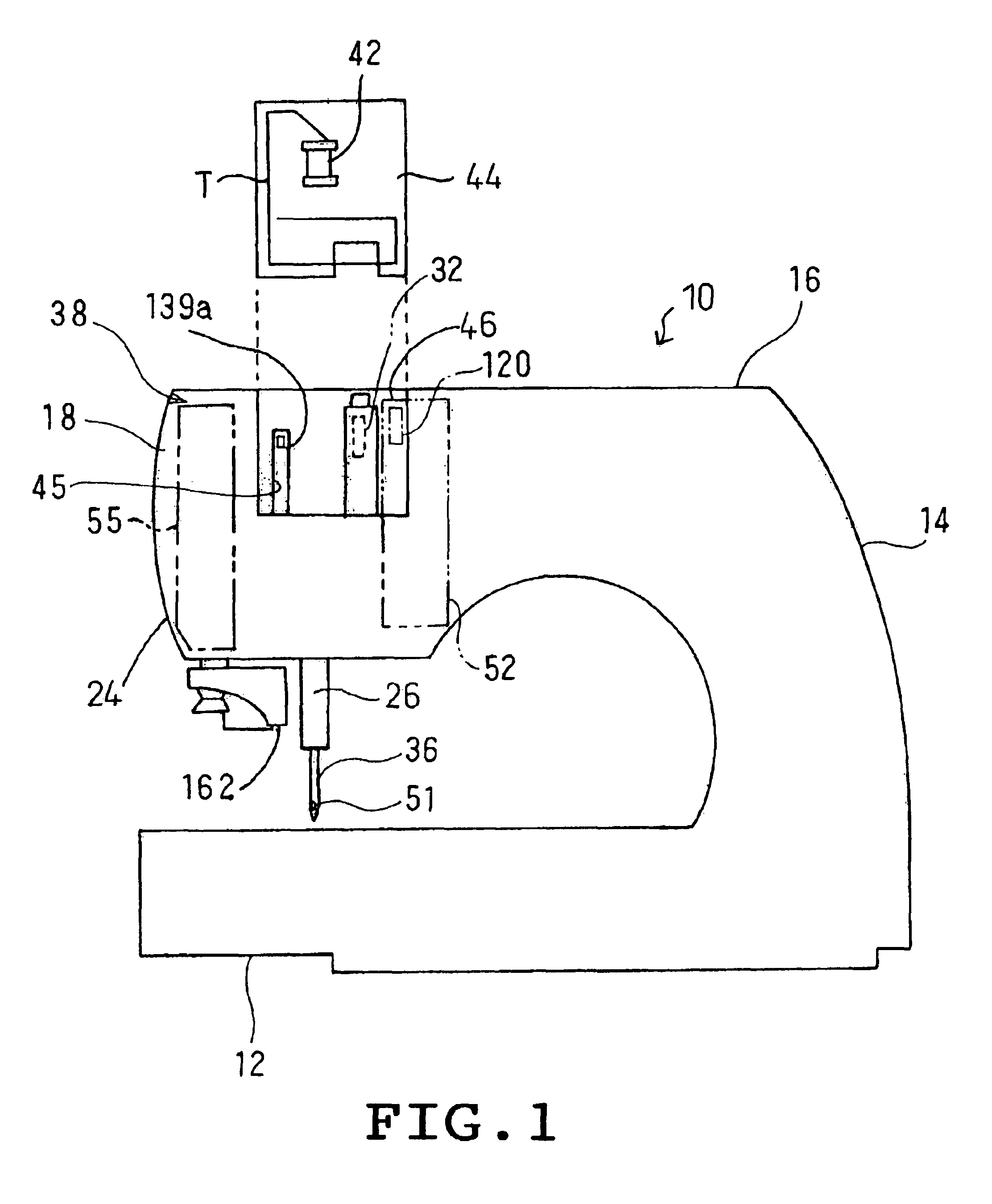
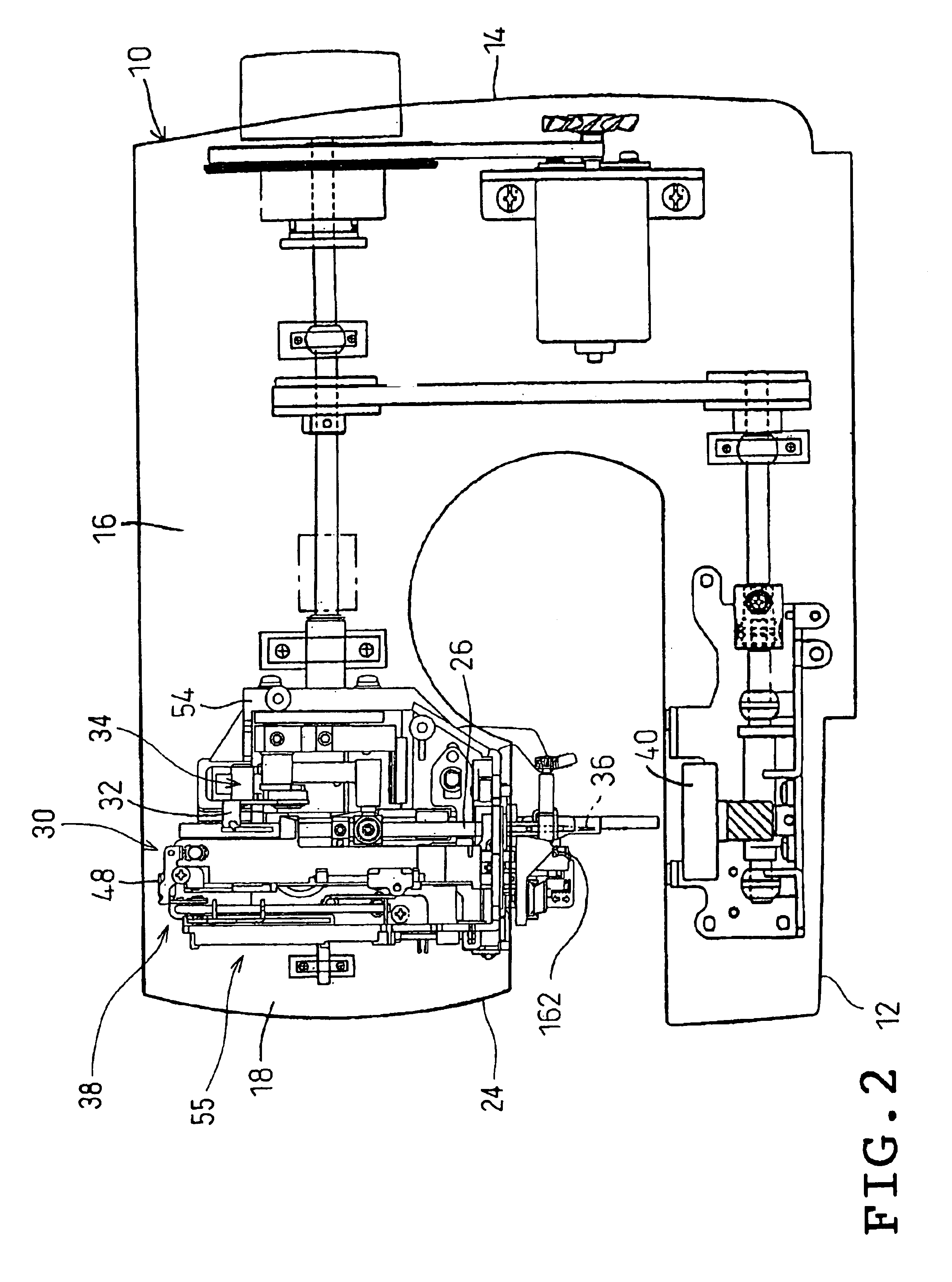
[0031]One embodiment of the invention will be described with reference to the accompanying drawings. Referring to FIGS. 1 and 2, a sewing machine 10 to which the threading apparatus of the invention is applied is schematically shown. The sewing machine 10 comprises a sewing bed 12 having a horizontal plane, a pillar 14 standing from a right end of the bed 12 and a sewing arm 16 extending rightward from an upper end of the pillar 14 and a machine head 18 located at a left end of the arm 16. A needle bar 26 extends downward from the head 18. A sewing needle 36 is detachably attached to a lower end of the needle bar 26. The head 18 encloses a needle bar driving mechanism 28 for moving the needle bar 26 up and down, a needle bar swinging mechanism 30 for swinging the needle bar 26 horizontally, a needle thread take-up driving mechanism 34 interlocked with the movement of the needle bar driving mechanism 28 for moving the needle thread take-up 32 up and down, and a threading mechanism 38...


PUM


Abstract

A sewing machine includes a sewing needle having an eye, a threading hook passed through the eye of the needle, a traveling mechanism for traveling the threading hook so that the threading hook is advanced through the eye of the needle and retreated through the eye of the needle, a thread holding member for holding the thread, a moving mechanism for moving the thread holding member between a first position where the thread holding member is close to the threading hook having been advanced through the eye of the needle and a second position where the thread holding member is away from the threading hook having been advanced through the eye of the needle, and a speed reducing mechanism for reducing a moving speed of the thread holding member while the thread holding member is holding the thread and being moved near the threading hook having been advanced through the eye of the needle.

Description

BACKGROUND OF THE INVENTION[0001]1. Field of the Invention[0002]This invention relates generally to sewing machines and more particularly to a sewing machine provided with a threading hook which passes a thread through a needle eye.[0003]2. Description of the Related Art[0004]JP-B-7-71596 discloses a threading apparatus for a sewing machine comprising a threading hook allowed to pass through a needle eye, a threading bar supporting the hook, a rotating member for rotating the hook only when the needle is located at a higher position than a predetermined position, a holding member for holding a needle thread at two positions, a moving mechanism for moving the holding member near the needle eye, and an operating member operated so that the threading bar is moved upward and downward and rotated.[0005]In the above-described threading apparatus, a moving speed of the hook is increased when a user operates the operating member quickly. Depending upon the environment where the sewing machi...

Claims


Application Information

Patent Timeline
Patent Type & Authority Patents(United States)
IPC IPC(8): D05B87/00D05B87/02
CPCD05B87/02
Inventor FUKAO, HIROAKI
Owner BROTHER KOGYO KK
Why Eureka
Try Eureka