Surgical stapling device with tissue tensioner

a tissue tensioner and surgical stapling technology, which is applied in the direction of surgical staples, paper/cardboard containers, manufacturing tools, etc., can solve the problems of malformed staples, ineffective removal of all desired tissue, and difficulty in properly positioning the tissue to be removed within the staple holding component of the surgical stapling device, etc., to achieve the effect of facilitating the movement of the tissue tensioner devi

Active Publication Date: 2005-11-01
TYCO HEALTHCARE GRP LP
View PDF204 Cites 1798 Cited by
  • Summary
  • Abstract
  • Description
  • Claims
  • Application Information

AI Technical Summary

Benefits of technology

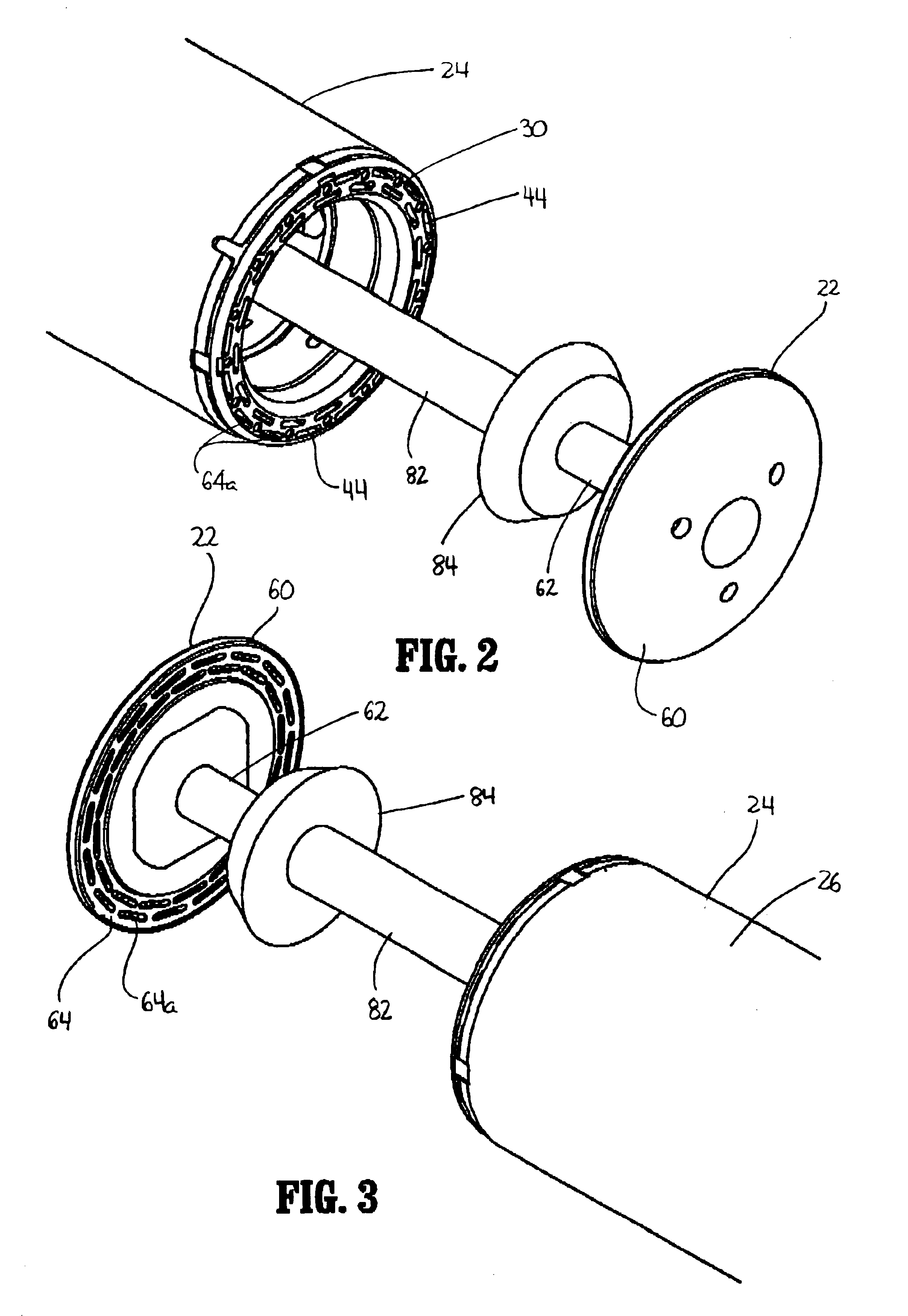
[0012]In another embodiment, one of the anvil shaft and the tissue tensioner shaft includes a series of indentations and the other of the anvil shaft and tissue tensioner shaft includes a projection or nub which is releasably received in one of the indentations to releasably retain the tissue tensioner device at a fixed position in relation to the anvil shaft. A predetermined force can be applied to the tissue tensioner trigger to disengage the nub from a respective indentation to facilitate movement of the tissue tensioner device in relation to the anvil and the shell assembly.

Problems solved by technology

Although the use of circular anastomosis staplers for hemorrhoid treatment has many benefits, some problems do exist.
For example, during approximation of the anvil head and staple holding component of the surgical stapling device, it is sometimes difficult to properly position tissue to be removed within the staple holding component of the surgical stapling device.
This may result in malformed staples and / or ineffective removal of all the desired tissue.

Method used


Image

  • Surgical stapling device with tissue tensioner
  • Surgical stapling device with tissue tensioner
  • Surgical stapling device with tissue tensioner

Examples


Embodiment Construction

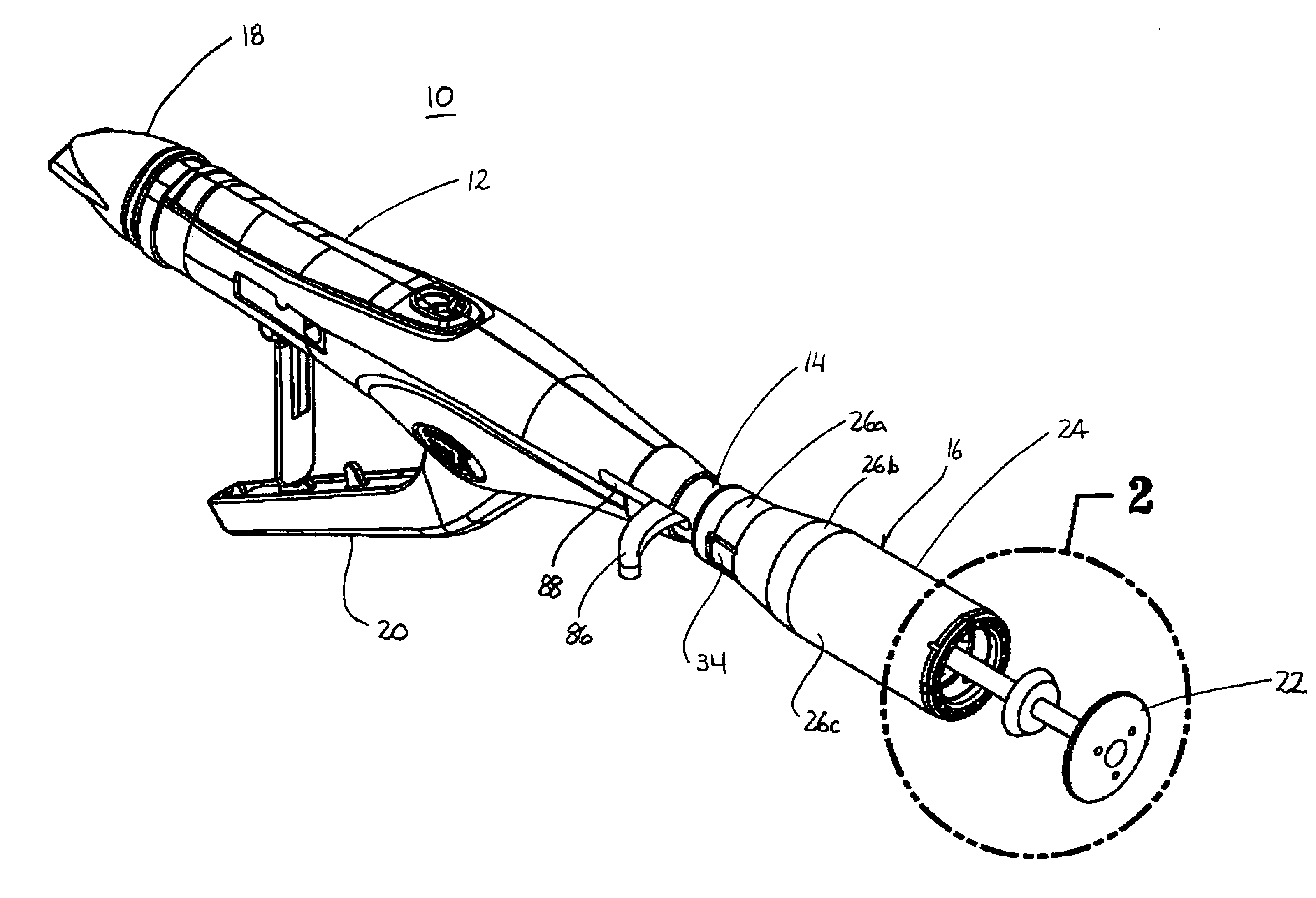
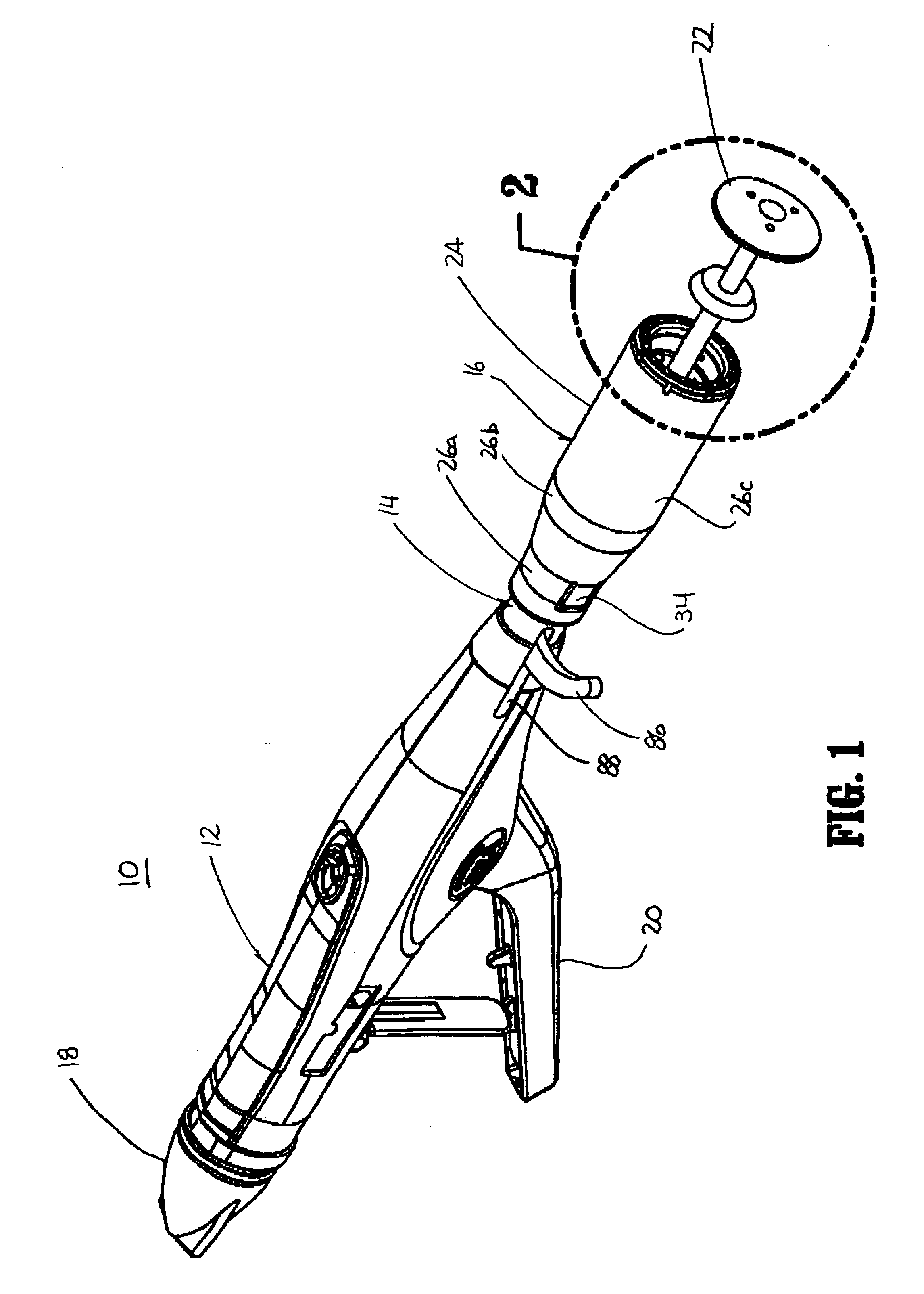
[0033]Embodiments of the presently disclosed surgical stapling device will now be described in detail with reference to the drawings in which like reference numerals designate identical or corresponding elements in each of the several views. Throughout this description, the term “proximal” will refer to the portion of the device closest to the operator and the term “distal” will refer to the portion of the device furthest from the operator. U.S. provisional application Ser. No. 60 / 480,074 (“'074 application”), entitled Surgical Stapling Device, filed Jun. 20, 2003, under Express Mail #EV328280895US is incorporated herein in its entirety by reference.

[0034]FIGS. 1-8 illustrate one embodiment of the presently disclosed surgical stapling device shown generally as 10. Referring to FIG. 1, surgical stapling device 10 includes a proximal handle assembly 12, a central body portion 14 and a distal head portion 16. Proximal handle assembly 12 is substantially identical to the handle assembly...


PUM

PropertyMeasurementUnit
diameteraaaaaaaaaa
forceaaaaaaaaaa
areaaaaaaaaaaa

Abstract

A circular stapling device particularly suited for surgical treatment of internal hemorrhoids is provided. The stapling device includes a distal head portion having an anvil and a shell assembly. A tissue tensioner device including a tissue engagement member is movably positioned between the anvil and the shell assembly and is operable via a tensioner trigger to position tissue within a bore defined within the shell assembly.

Description

[0001]This application claims priority from U.S. provisional application Ser. No. 60 / 487,841 filed Jul. 16, 2003, the entire contents of which are incorporated herein by reference.BACKGROUND[0002]1. Technical Field[0003]The present disclosure relates generally to a surgical device for treating hollow tissue organs. More particularly, the present disclosure relates to a surgical stapling device suitable for the treatment of internal hemorrhoids.[0004]2. Background of Related Art[0005]Anastomosis is the surgical joining of separate hollow organ sections. Typically, an anastomosis procedure follows surgery in which a diseased or defective section of hollow tissue is removed and the remaining end sections are to be joined. Depending on the desired anastomosis procedure, the end sections may be joined by either circular, end-to-end or side-to-side organ reconstruction methods.[0006]In a known circular anastomosis procedure, two ends of organ sections are joined by means of a stapling dev...

Claims


Application Information

Patent Timeline
Patent Type & Authority Patents(United States)
IPC IPC(8): A61B17/115A61B17/03A61B17/32
CPCA61B17/115A61B17/1114A61B17/1155A61B17/32053
Inventor HEINRICH, RUSSELL
Owner TYCO HEALTHCARE GRP LP
Why Eureka
Try Eureka