Electronic camera having an automatic electric flash function

an electric flash and electronic camera technology, applied in the field of electronic cameras, can solve the problems of underexposure and the inability of the flash apparatus to emit light in an optimal amount, and achieve the effect of better exposur

Active Publication Date: 2005-11-01
OM DIGITAL SOLUTIONS CORP
View PDF9 Cites 12 Cited by
  • Summary
  • Abstract
  • Description
  • Claims
  • Application Information

AI Technical Summary

Benefits of technology

[0007]An object of the present invention is to provide an electronic ca...

Problems solved by technology

However, underexposure may occur if the amount of light emitted to the object is insufficient, because the gain is fixed in the process of photographing the object.
The flash app...

Method used


Image

  • Electronic camera having an automatic electric flash function
  • Electronic camera having an automatic electric flash function
  • Electronic camera having an automatic electric flash function

Examples


Embodiment Construction

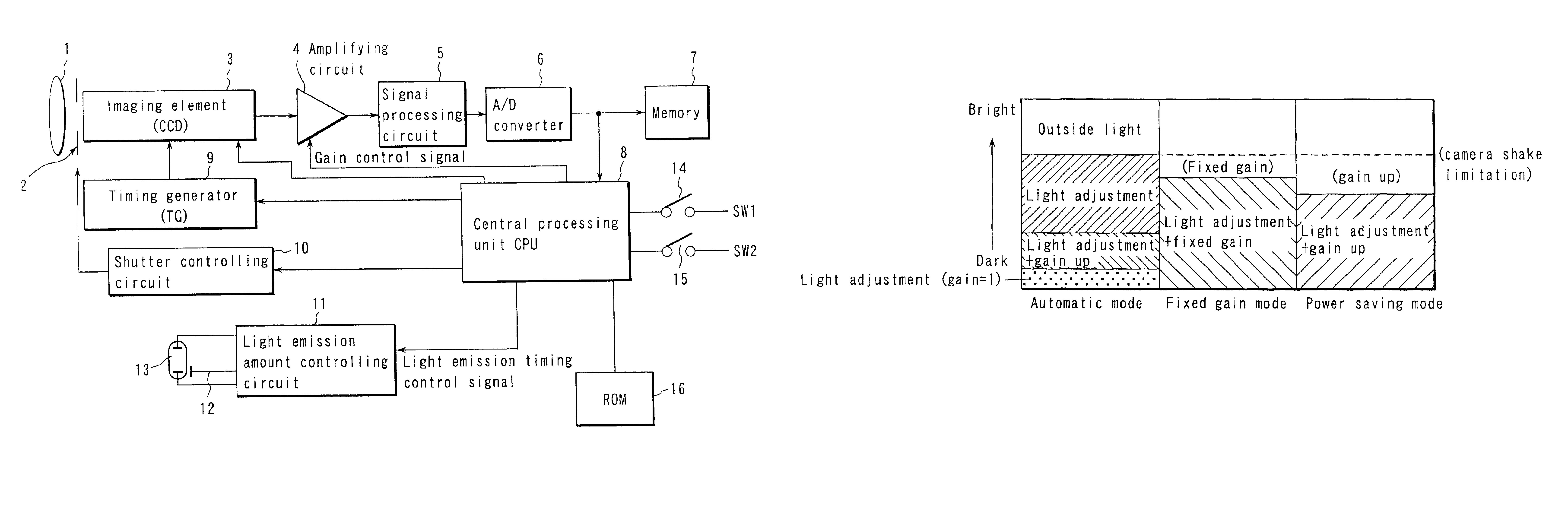
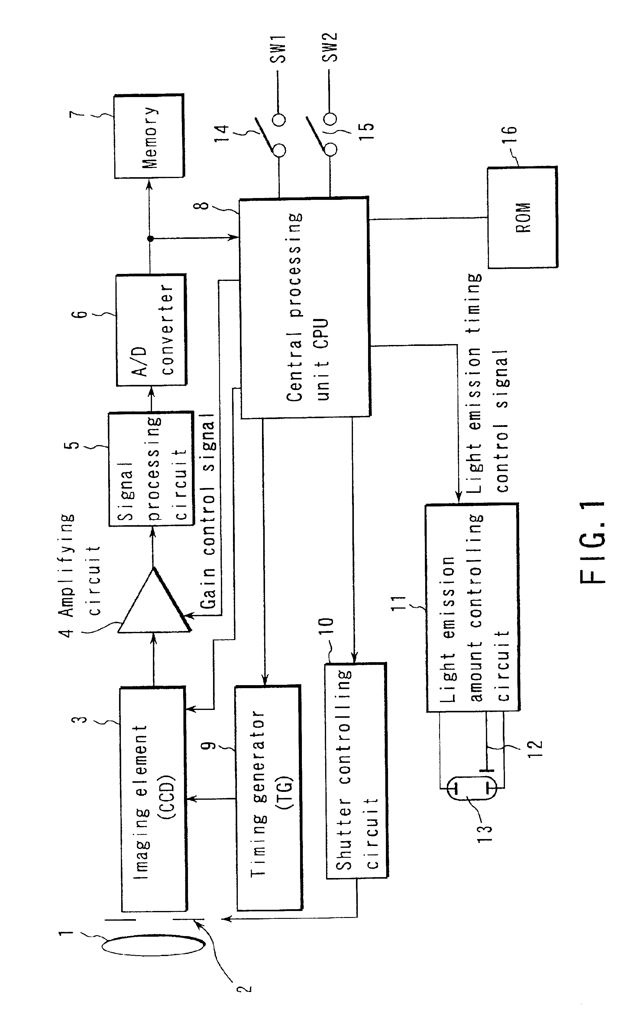
[0032]An embodiment of the present invention will be explained with reference to the drawings below. FIG. 1 illustrates a configuration of an electronic camera according to an embodiment of the present invention.

[0033]An electronic camera according to the present embodiment comprises a lens 1 for inputting the image of an object, a shutter 2 used as well as an aperture, and a imaging element 3 such as a charge-coupled device (CCD) or the like. The imaging element 3 receives the light reflect from the object prior to the photographing of the object and converts the light into electricity. The imaging element 3 forms an image of the object from the light incident into the lens 1. The camera further comprises an amplifying circuit 4 for amplifying the image signal generated by the imaging element 3, a signal processing circuit 5 for sampling and holding the image signal amplified by the amplifying circuit 4, an A / D converter 6 for converting a signal from the signal processing circuit ...


PUM


Abstract

An electronic camera, which is capable of obtaining a more appropriate exposure even when taking a picture by an electric flash photograph, comprises a light emission section for emitting a preliminary light prior to a main photograph and emitting a main light upon taking a picture with respect to a object, a pickup device for receiving an object image in the preliminary light emission and converting a light into electricity to obtain a photograph signal, an amplifying section for amplifying the photograph signal which is obtained by the pickup device and a setting section for setting a gain of the amplifying section and a light emission amount in the main light emission on the basis of the photograph signal obtained in the preliminary light emission.

Description

CROSS-REFERENCE TO RELATED APPLICATIONS[0001]This application is based upon and claims the benefit of priority from the prior Japanese Patent Application No. 2000-249653, filed Aug. 21, 2000, the entire contents of which are incorporated herein by reference.BACKGROUND OF THE INVENTION[0002]1. Field of the Invention[0003]The present invention generally relates to an electronic camera. More particularly, the present invention relates to an electronic camera having an automatic electric flash function.[0004]2. Description of the Related Art[0005]An electric flash apparatus having an amplifying circuit is disclosed in Jpn. Pat. Appln. KOKAI Publication No. 11-84489. The amplifying circuit receives image signals generated from light beams reflected from an object and amplifies the image signals with different gains. The amount in which light should be emitted to the object to photograph it is calculated from the image signals thus amplified. Hence, light can be emitted in an optimal amou...

Claims


Application Information

Patent Timeline
IPC IPC(8): G03B17/48G03B7/16G03B15/03G03B15/05G03B19/02H04N5/225H04N5/235H04N5/238H04N101/00
CPCG03B17/48H04N5/2352H04N5/2354H04N2101/00H04N23/72H04N23/74
Inventor HIGUCHI, MASAYU
Owner OM DIGITAL SOLUTIONS CORP
Why Eureka
Try Eureka