Apparatus and method for dampening disk vibration in storage devices

Inactive Publication Date: 2005-11-01
SAMSUNG ELECTRONICS CO LTD
View PDF19 Cites 7 Cited by
  • Summary
  • Abstract
  • Description
  • Claims
  • Application Information

AI Technical Summary

Benefits of technology

[0020]The reduced distance, or air gap, between the dampening surface of the dampening mechanism and rotating disk surface inhibits the creation of the back flow of air between the rotating disk surface and dampening surface. The air gap may also minimize the

Problems solved by technology

These aerodynamic forces may act upon a read-write head assembly, its actuator, and the rotating disk causing disk fluttering, head-positioning errors and read-write errors.
This back flow of air may act upon the disk surface, causing

Method used


Image

  • Apparatus and method for dampening disk vibration in storage devices
  • Apparatus and method for dampening disk vibration in storage devices
  • Apparatus and method for dampening disk vibration in storage devices

Examples


Embodiment Construction

[0052]The rotational velocity of a disk surface of a rotating disk, or rotating disks, may affect significant aerodynamic forces in an air cavity in which the disk, or disks rotate. These aerodynamic forces may act upon a read-write head assembly, its actuator, and the rotating disk causing head-positioning and read-write errors and disk fluttering.

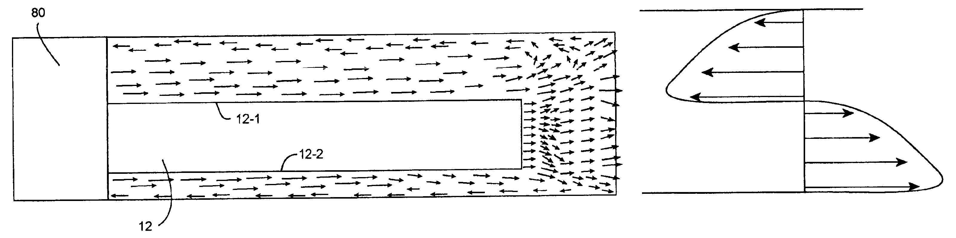
[0053]As stated in the summary, a boundary layer is an air region near a solid surface with essentially no relative velocity with regards to that surface. This region is caused by the effect of friction between the solid surface and the air. The depth of this region is roughly proportional to the square root of the viscosity divided by the velocity of the surface.

[0054]FIG. 2A illustrates a cross section view of a spindal motor 80 and one disk 12 with air flow between the upper disk surface 12-1 and top disk cavity face, as well as air flow between the lower disk surface 12-2 and bottom disk cavity face. The disk surface is rotating at an...


PUM


Abstract

Aerodynamic forces contribute to disk and actuator vibration leading to track positioning errors in storage devices such as hard disk drives. The invention provides a variety of dampening mechanisms and a method of dampening to alleviate these problems.

Description

CROSS REFERENCE TO RELATED APPLICATIONS[0001]This application is a continuation-in-part of application Ser. No. 10 / 100,960, filed Mar. 18, 2002 now U.S. Pat. No. 6,771,458, and this application claims the benefit of U.S. Provisional Application No. 60 / 290,128, filed May 10, 2001.TECHNICAL FIELD[0002]This invention relates to dampening mechanisms in storage devices that reduce vibrations in a disk rotating in such a storage device.BACKGROUND ART[0003]Disk drives are an important data storage technology. Read-write heads directly communicate with a disk surface containing the data storage medium over a track on the disk surface.[0004]FIG. 1A illustrates a typical prior art hard disk drive, which may be a high capacity disk drive 10. Disk drive 10 includes an actuator arm 30 that further includes a voice coil 32, actuator axis 40 suspension or head arms 50. A slider / head unit 60 is placed among data storage disks 12.[0005]FIG. 1B illustrates a typical prior art high capacity disk drive...

Claims


Application Information

Patent Timeline
IPC IPC(8): G11B33/08G11B25/04G11B17/02
CPCG11B33/08G11B17/02
Inventor KANG, SEONG WOOKIM, SEONG HOONTRAN, GREGORYNGUYEN, VINCENTTAM, SCOTTIVANOV, NIKOLLAYBRAGG, JOE
Owner SAMSUNG ELECTRONICS CO LTD
Why Eureka
Try Eureka