Multimodality medical imaging system and method with separable detector devices

a multi-modality, detector device technology, applied in the direction of radiation beam directing means, instruments, applications, etc., can solve the problems of claustrophobia, other discomfort or stress in the patient, less desirable use, and additional time and effort required to extend or withdraw the patient from either end of the multi-modality scanner bor

Inactive Publication Date: 2005-11-01
KONINKLIJKE PHILIPS ELECTRONICS NV
View PDF22 Cites 113 Cited by
  • Summary
  • Abstract
  • Description
  • Claims
  • Application Information

AI Technical Summary

Problems solved by technology

Moreover, the relatively lengthy isolation of the patient within the tight quarters of the bore can cause anxiety, such as claustrophobia, and other discomfort or stress in the patient.
These shortcomings of multimodality cameras make their use less desirable when all modalities of imaging are not required.
Nevertheless, should interventional applications or other procedure require direct access to a patient by a caregiver, additional time and effort will be required to extend or withdraw the patient from either end of the multimodality scanner bore.
Moreover, unnecessary levels of patient discomfort, stress and anxiety result.

Method used


Image

  • Multimodality medical imaging system and method with separable detector devices
  • Multimodality medical imaging system and method with separable detector devices
  • Multimodality medical imaging system and method with separable detector devices

Examples


Embodiment Construction

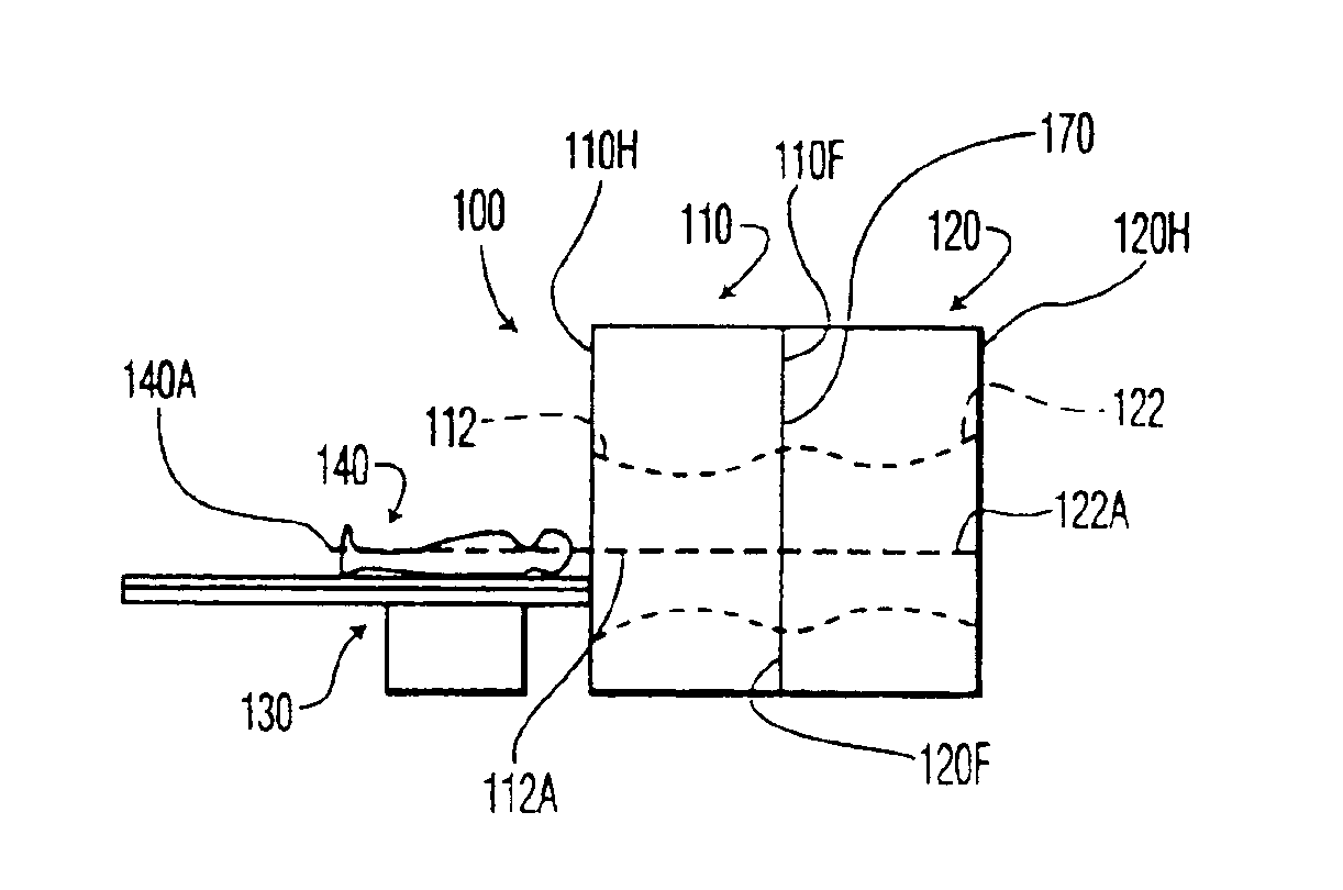
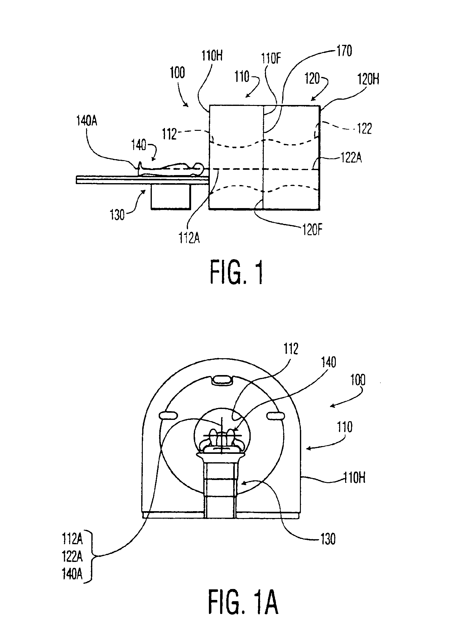
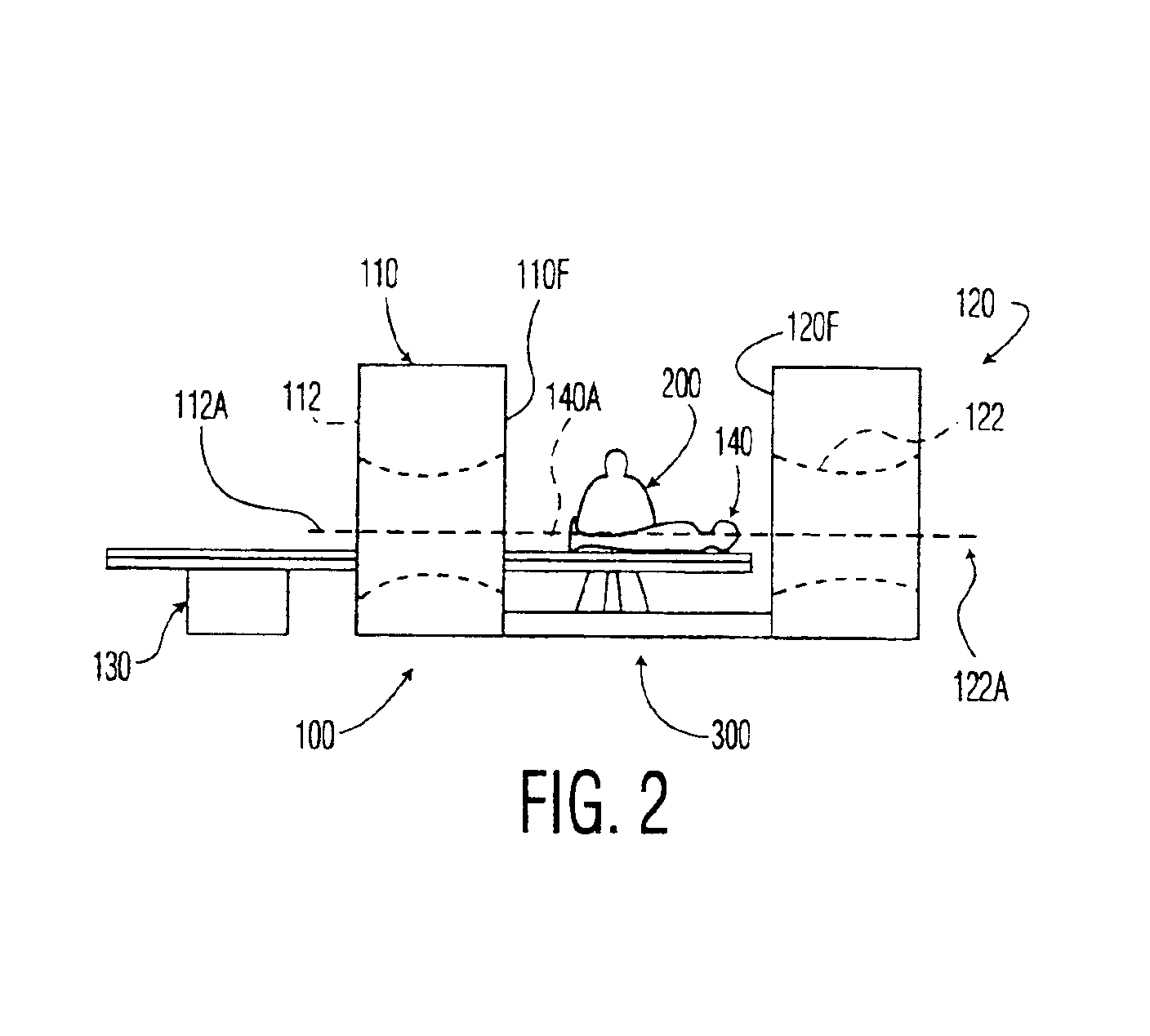
[0027]Shown in FIG. 1 is a multimodality medical imaging system scanner assembly 100, having first and second imaging devices 110 and 120. In the embodiment shown, each of the imaging devices 110 and 120 comprise at least a scanner having a modality of operation, and may also include associated scanner support structure and associated electronics. Further, in the embodiment shown, each of the imaging devices 110 and 120 includes a scanner opening or bore 112 and 122 (shown by broken lines), respectively, through which a patient table 130 extends and translates a subject patient 140 during a scanning operation. It will be apparent that imaging devices 110 and 120 may alternatively utilize scanners or detectors that obtain information about the patient 140 without being configured to form a bore, such as a partial closure, an arrangement of one or more planar detectors and other configurations capable of obtaining patient information. Moreover, it will be apparent that while scanner b...


PUM


Abstract

The invention comprises a system and method for creating medical images of a subject patient using a plurality of imaging devices, such as tomographic imaging scanners. The imaging devices each have a bore through which a patient is translated during scanning. The imaging devices can be moved apart to allow greater access to a patient between the bores.

Description

TECHNICAL FIELD[0001]The invention relates to multimodality medical imaging systems for viewing anatomical structures and functions of a patient, such as combined x-ray Computed Tomography (CT) and Positron Emission Tomography (PET) scanners and, more particularly, to separating the scanners to facilitate use of one scanner independently of the other scanner.BACKGROUND OF THE INVENTION[0002]Tomographic imaging devices or cameras are frequently used to assist in the diagnosis and treatment of a variety of anatomical structures and physiologic functions within the body of a subject patient, while minimizing the need for invasive procedures. Such devices typically utilize scanners that obtain data or information about such structures and functions from the patient at specified, discrete locations along the length of a patient. Using this information, the camera produces a series of images, each depicting a cross-section of the body of the patient, in a plane generally perpendicular to ...

Claims


Application Information

Patent Timeline
Patent Type & Authority Patents(United States)
IPC IPC(8): A61B6/00A61B5/055A61B8/00G01R33/30A61B6/03G01T1/161
CPCA61B6/032A61B6/037A61B6/4417A61B6/5235A61B8/5238A61B8/00Y10S128/906
Inventor DESILETS, MARKHINES, HORACE H.WELLNITZ, DONALD
Owner KONINKLIJKE PHILIPS ELECTRONICS NV
Why Eureka
Try Eureka