Drift tracking feedback for communication channels

a technology of drift tracking and communication channels, applied in the direction of instruments, generating/distributing signals, baseband system details, etc., can solve the problem of choosing phase values that are not optimal, and achieve the effect of efficient tracking of drifting channel properties

Active Publication Date: 2005-11-01
RAMBUS INC
View PDF57 Cites 62 Cited by
  • Summary
  • Abstract
  • Description
  • Claims
  • Application Information

AI Technical Summary

Benefits of technology

[0006]The present invention provides a system and method for setting a parameter of a communication channel, which allows for optimizing the parameter while efficiently tracking drift of properties of the channel. A communication channel includes a first component having a transmitter coupled to a normal signal source, and a second component having a receiver coupled to a normal signal destination. A communication link couples the first and second components. The communication system provides for setting an operation value for the parameter, which for example can include executing an exhaustive calibration sequence at initialization of the channel. The method and system of the present invention provides for tracking drift in the parameter by monitoring a signal on another channel that is characterized by drift relative to a reference, such as a reference clock, in amounts that correlate with drift in the parameter of communication channel relative to the reference, and to update, or indicate the need for updating, the operation value of the parameter in response to the monitoring function. The signal being monitored is provided in various ways according to embodiments of the invention, including by signals on channels that emulate the channel being monitored, by signals on another channel within a single communication bus, by signals on a channel that loops back to a component on the channel that generates it, or by signals that otherwise exhibit characteristics that correlate, whether causally or not, to the parameter being tracked on the channel.

Problems solved by technology

However, once these phase values are set, offsets due to system conditions (such as temperature effects on the propagation time of the wires in the link) will cause the chosen phase values to become non-optimal.

Method used


Image

  • Drift tracking feedback for communication channels
  • Drift tracking feedback for communication channels
  • Drift tracking feedback for communication channels

Examples


Embodiment Construction

[0022]A detailed description of embodiments of the present invention is provided with reference to the Figures.

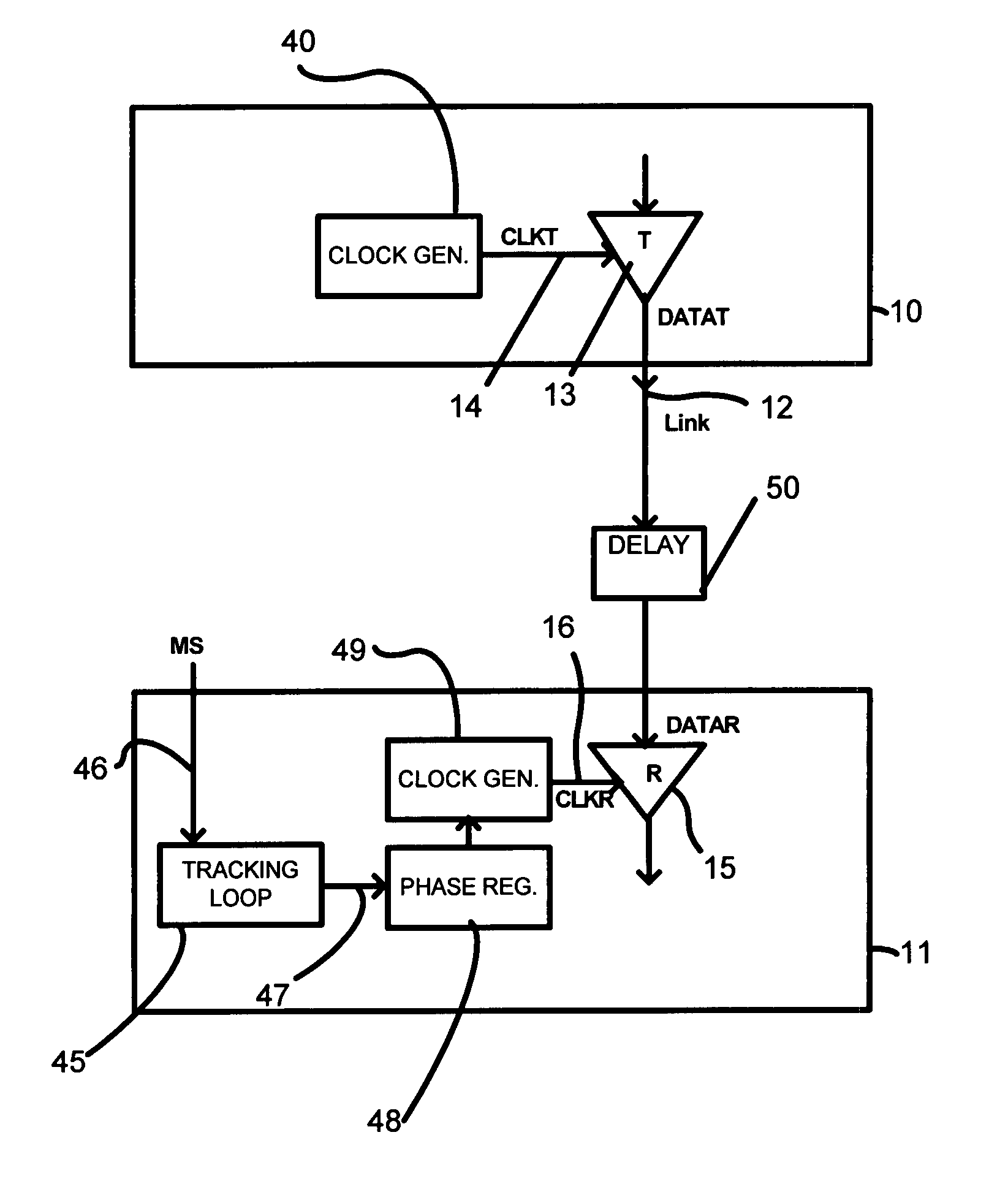
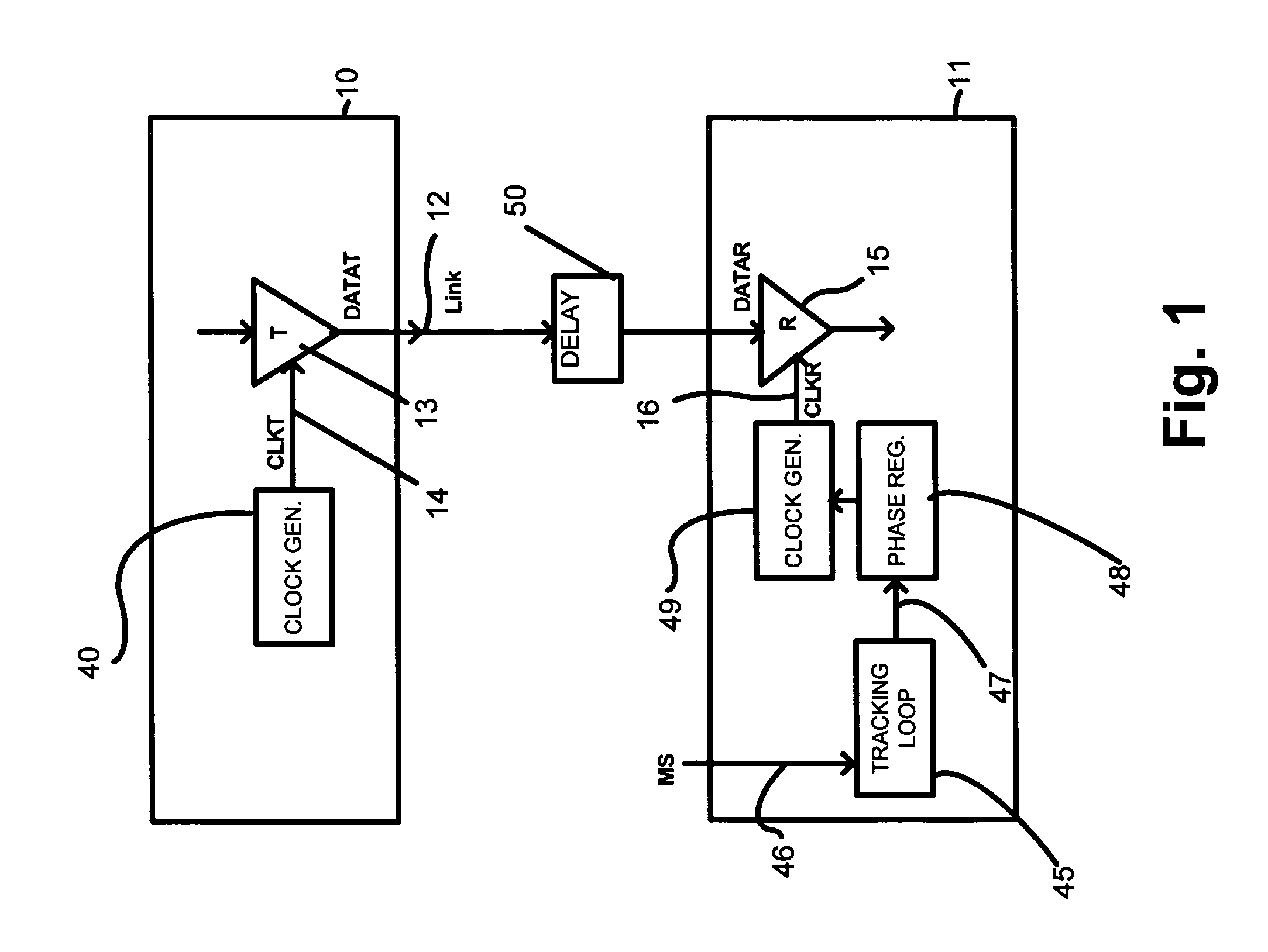
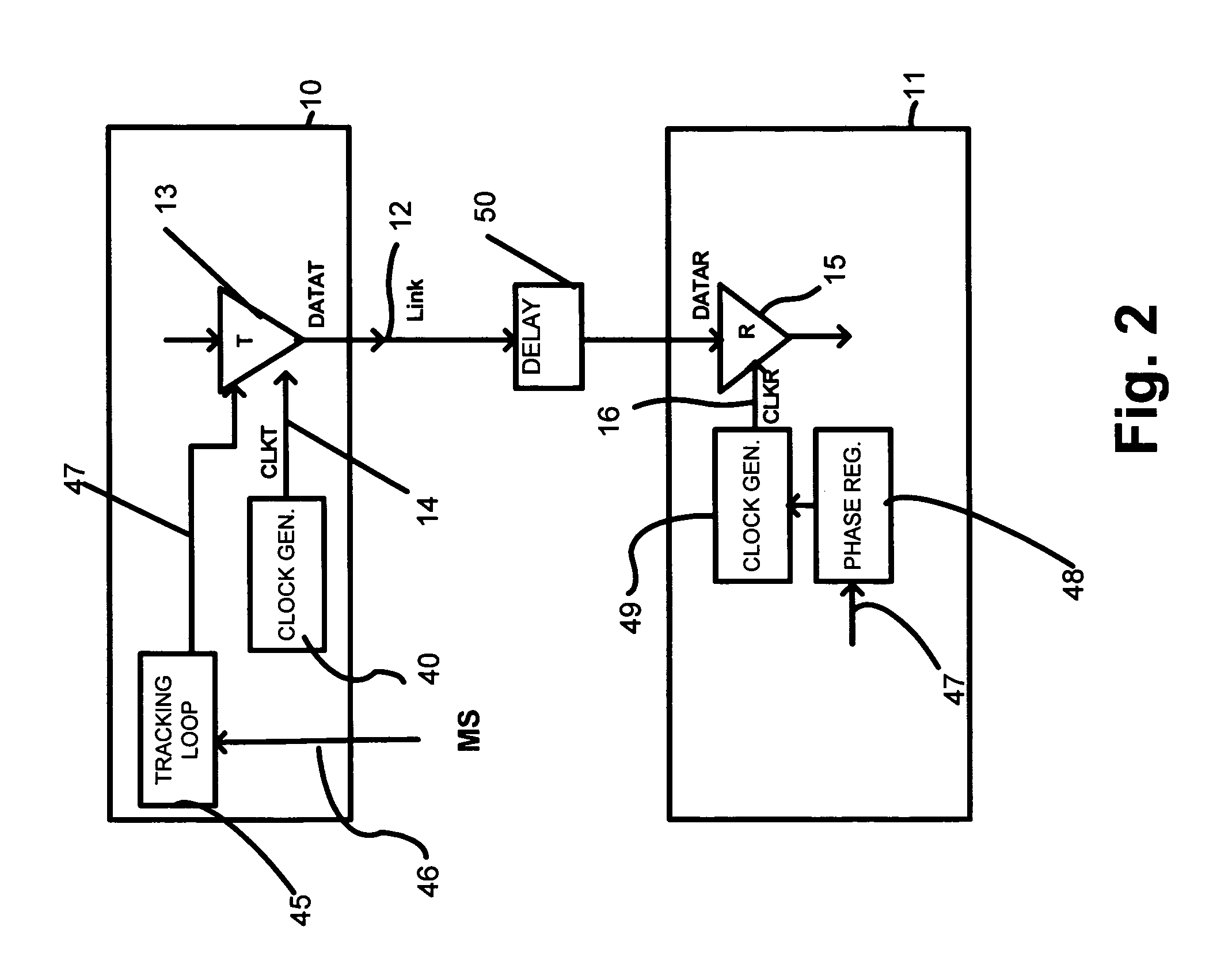
[0023]FIG. 1 shows two components 10, 11 connected with an interconnection medium, referred to as link 12. Component 10 has a transmitter circuit 13 which drives symbols (bits) on link 12 in response to timing events on the internal CLKT signal 14. This series of bits forms signal DATAT. Component 11 has a receiver circuit 15 which samples symbols (bits) on link 12 in response to timing events on the internal CLKR signal 16. The DATAT forms signal DATAR at the opposite end of the link, which is sampled by the receiver. The transmit clock CLKT is generated by a transmit clock generator 40. The receive clock CLKR is generated by a receive clock generator 49 that is responsive to a phase control signal stored in a phase calibration register 48. A communication channel between the components 10 and 11 comprises the transmitter circuit 13, the link 12 and the receiver circuit 15...


PUM


Abstract

A communication channel includes a first component having a transmitter coupled to a normal signal source, and a second component having a receiver coupled to a normal signal destination. A communication link couples the first and second components. Calibration logic provides for setting an operation value for a parameter of the communication channel, such as by executing an exhaustive calibration sequence at initialization of the link. A tracking circuit, including a monitoring function, tracks drift in the parameter by monitoring a feedback signal that has a characteristic that correlates with drift in the communication channel, and updates, or indicates the need for updating of, the operation value of the parameter in response to the monitoring function.

Description

BACKGROUND OF THE INVENTION[0001]1. Field of the Invention[0002]The present invention relates to the calibration of communication channel parameters in systems, including mesochronous systems, in which two (or more) components communicate via an interconnection link; and to the calibration needed to account for drift of conditions related to such parameters during operation of the communication channels.[0003]2. Description of Related Art[0004]In high-speed communication channels, including channels which are operated in a mesochronous manner, a transmitter and receiver are each locked to a specific phase relative to some global reference clock. The phase values of the transmitter and receiver which minimize the bit-error-rate of the communication channel may be determined in a number of ways. However, once these phase values are set, offsets due to system conditions (such as temperature effects on the propagation time of the wires in the link) will cause the chosen phase values to ...

Claims


Application Information

Patent Timeline
Patent Type & Authority Patents(United States)
IPC IPC(8): G06F1/04H04L7/00H04L7/10H04L25/14
CPCG11C29/02G11C29/022G11C29/028G11C29/50012H04L7/0008H04L7/0091H04L7/033H04L7/10H04L25/14H04L7/0033H04L7/0004G06F1/08G06F1/12
Inventor BEST, SCOTT C.ABHYANKAR, ABHIJIT M.CHANG, KUN-YUNGLAMBRECHT, FRANK
Owner RAMBUS INC
Why Eureka
Try Eureka