Constant bypass flow controller for a variable displacement pump

Active Publication Date: 2005-11-08
TRIUMPH ENGINE CONTROL SYST
View PDF71 Cites 25 Cited by
  • Summary
  • Abstract
  • Description
  • Claims
  • Application Information

AI Technical Summary

Benefits of technology

[0009]The subject invention is directed to a pump control system for a variable displacement fuel pump such that the pump displacement exceeds the required steady state flow of the associate

Problems solved by technology

Consequently, under many operating conditions, large amounts of pressurized fuel are returned to the pump inlet for recirculation.
The return and recirculation results in significant fuel heating due to additional energy being put into the fuel which is subsequently turned into heat as the pressure drops in the recirculation path.
In modern designs, fuel heating is a critical issue because the fuel is typically used as a heat exchanger to maintain proper operating temperature.
Other methods of heat exchange are undesirable because of the associated size, weight and cost.
Under such rapidly varying

Method used


Image

  • Constant bypass flow controller for a variable displacement pump
  • Constant bypass flow controller for a variable displacement pump

Examples


Embodiment Construction

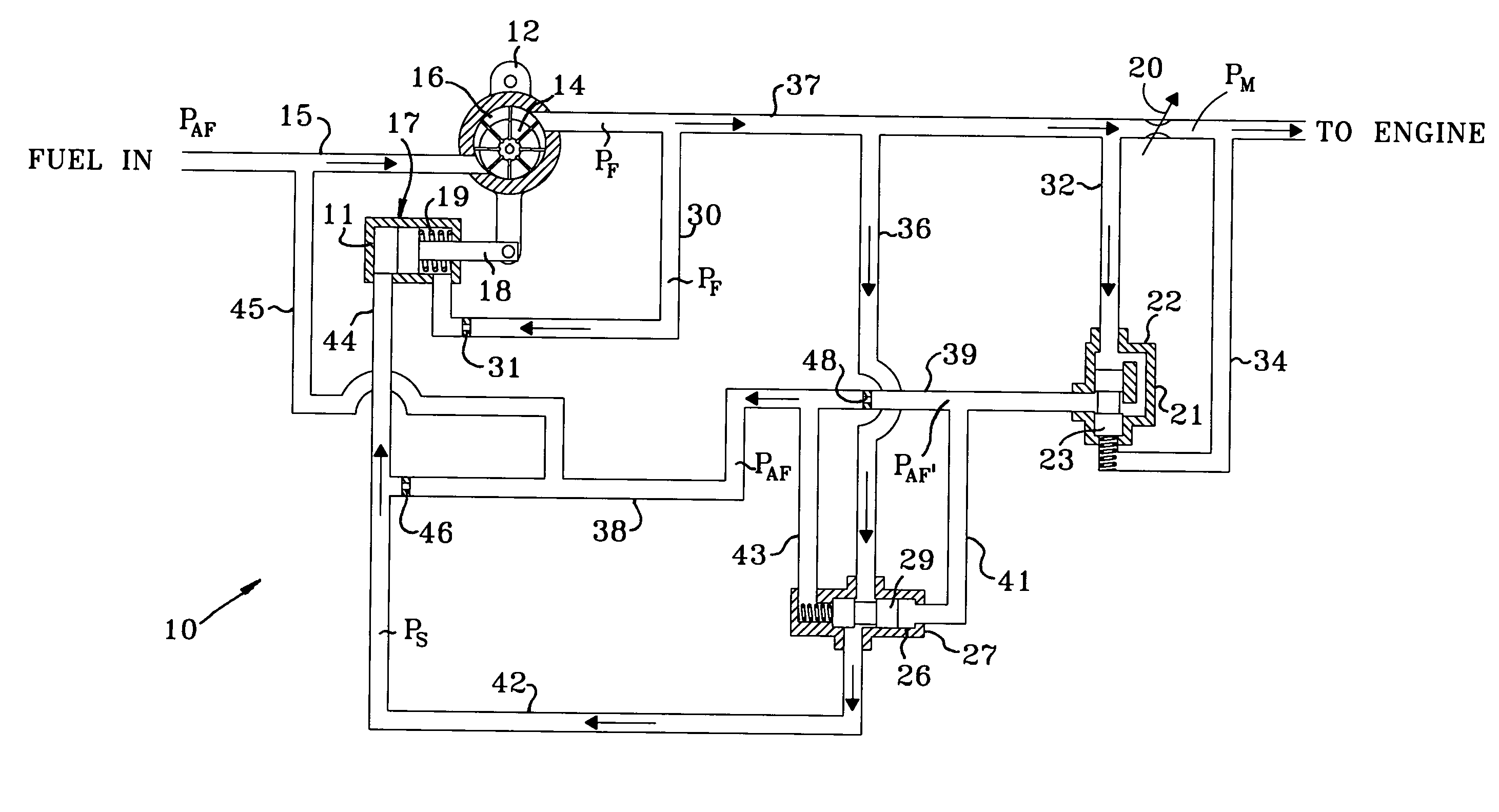
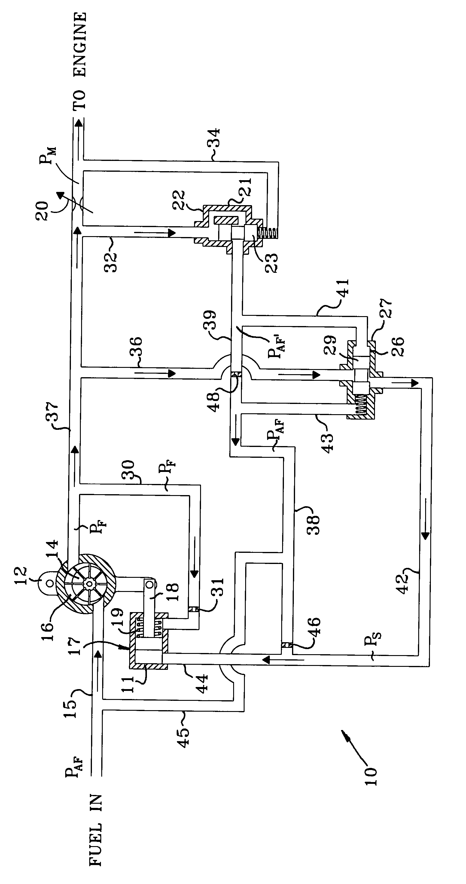
[0017]Referring now to Sole FIGURE, there is illustrated a schematic representation of the fuel control system of the subject invention which is designated generally by reference numeral 10. For clarity throughout the following description, arrows are shown within the lines of system 10 to indicate the direction in which the fuel flows and an annotated letter “P” is shown to indicate a pressure at certain locations. All relative descriptions herein such as left, right, up, and down are with reference to the system 10 as shown in Sole FIGURE and not meant in a limiting sense. Additionally, for clarity common items such as filters and shut off solenoids have not been included in the schematic representation of Sole FIGURE. System 10 is illustrated in association with a variable displacement vane pump 12. System 10 maintains the output flow of the pump 12 to meet engine needs yet advantageously minimizes recirculation, e.g., spill return flow which prevents excessive energy from being ...


PUM


Abstract

A fuel metering unit for controlling a variable displacement pump including a main metering valve in fluid communication with the pump for metering an output of the pump, a pressure regulator in fluid communication with the metering valve to create a spill return and a control valve in fluid communication with the pressure regulator and the pump for regulating the spill return flow so the spill return flow is maintained substantially constant at a low level to minimize the heat generated by recirculation by setting a displacement of the pump.

Description

CROSS-REFERENCE TO RELATED APPLICATION[0001]This application claims priority to U.S. Provisional Patent Application No. 60 / 462,652, filed Apr. 14, 2003, which is incorporated herein by reference.BACKGROUND OF THE INVENTION[0002]1. Field of the Invention[0003]The subject invention is directed generally to a system for regulating fluid flow, and more particularly, to a system for regulating the flow of fuel from a variable displacement pump utilizing bypass flow.[0004]2. Background of the Related Art[0005]Fixed delivery fuel pumps have often been sized to provide excessive fuel flow capacity in order to insure adequate supply to the associated engine. Consequently, under many operating conditions, large amounts of pressurized fuel are returned to the pump inlet for recirculation. The return and recirculation results in significant fuel heating due to additional energy being put into the fuel which is subsequently turned into heat as the pressure drops in the recirculation path. In mod...

Claims


Application Information

Patent Timeline
IPC IPC(8): F02M37/04B67D7/66
CPCF02M37/045
Inventor BENNETT, GEORGE L.DALTON, WILLIAM H.ZAGRANSKI, RAYMOND D.
Owner TRIUMPH ENGINE CONTROL SYST
Why Eureka
Try Eureka