Electrical connector having improved structure regarding terminals

a technology of electrical connectors and terminals, applied in the direction of coupling device connections, coupling protective earth/shielding arrangements, securing/insulating coupling contact members, etc., can solve the problems of signal shut off, poor orientation ability, and non-protective contacts

Inactive Publication Date: 2005-11-08
HON HAI PRECISION IND CO LTD
View PDF15 Cites 54 Cited by
  • Summary
  • Abstract
  • Description
  • Claims
  • Application Information

AI Technical Summary

Benefits of technology

[0007]It is an object of the present invention to provide an electrical connector having securing structure for preventing the terminals from warp even breaking off.
[0008]It is another object of the present invention to provide an electrical connector having better heat-radiation function.

Problems solved by technology

However, a bare periphery of those contacts makes them vulnerable and having poor orientation ability.
Therefore, when a complementary connector is inserted into the power connector, once the insertion direction has just a little deflection, those non-protective contacts would be forced and tend to warp even breaking off, which may results in signals shut off.
Furthermore, distal ends of all terminals locked in the housing are not in favor of radiating heat resulting from transmitting of signals in high speed connectors.

Method used


Image

  • Electrical connector having improved structure regarding terminals
  • Electrical connector having improved structure regarding terminals
  • Electrical connector having improved structure regarding terminals

Examples


Embodiment Construction

[0016]Reference will now be made to the drawing figures to describe the present invention in detail.

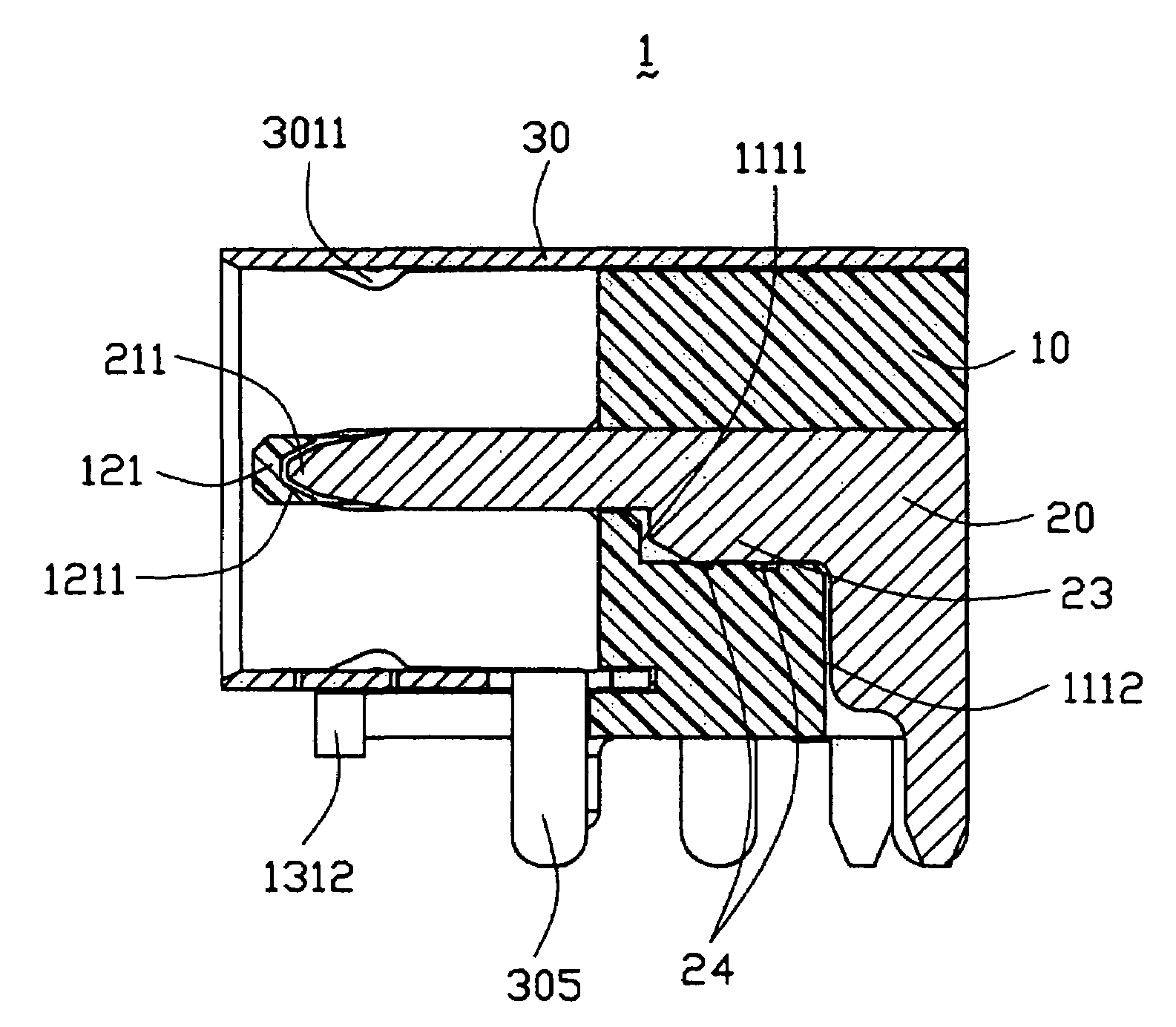
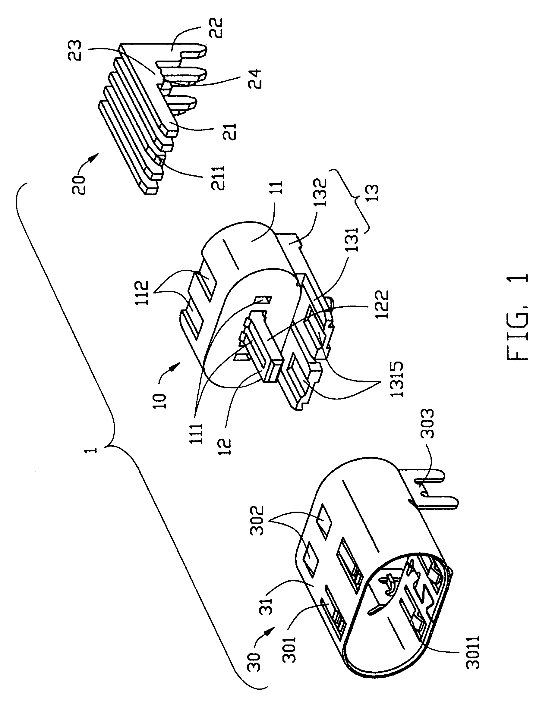
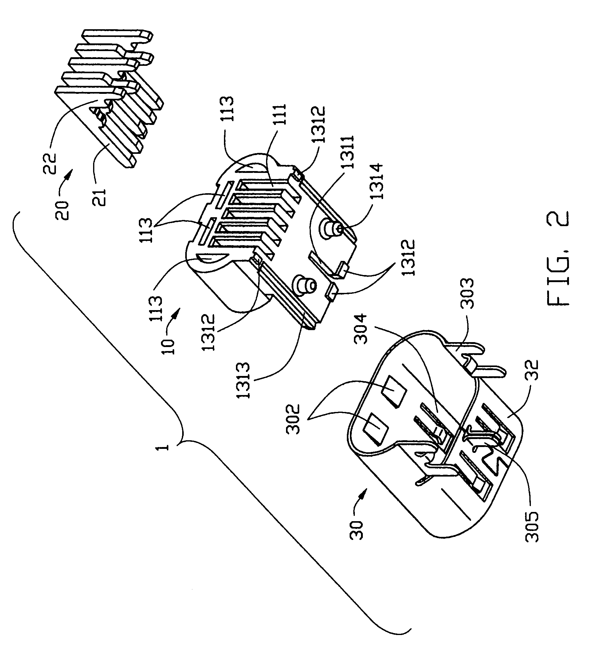
[0017]With reference to FIGS. 1–2, an electrical connector 1 in accordance with the present invention comprises an insulative housing 10, five terminals 20 received in the housing 10 and a shell 30 surrounding the housing 10. In this embodiment, only the third terminal 20 engaging with the insulative housing 10 is shown for illustrating the objects of this invention aforementioned.

[0018]The insulative housing 10 comprises a base portion 11 with an approximately elliptic cross-section, and five receiving passageways 111 extending through the base portion 11 along a front-to-back direction. A plate-like tongue portion 12 with two outer flanks 122 extends forwardly from a front face (not labeled) of the base portion 11. The third passageway 111 further extends onwards into and vertically runs through the tongue portion 12, until a certain distance is left to the front part thereof. In pr...


PUM


Abstract

An electrical connector (1) includes an insulative housing (10), a plurality of terminals (20) received in the housing, and a shell (30) surrounding the housing. The insulative housing includes a base portion (11) defining a plurality of passageways (111) extending therethrough, and a tongue portion (12) extending forwardly from the base portion. One of the passageways extends from the base portion into the tongue portion. One of the terminals is located adjacent to and outside of the tongue portion.

Description

BACKGROUD OF THE INVENTION[0001]1. Field of the Invention[0002]The present invention generally relates to an electrical connector, and particularly relates to an electrical connector having improved structure regarding terminals. This application relates to a contemporaneously filed application titled “ELECTRICAL CONNECTOR HAVING STRUCTURE FOR PREVENTING DEFLECTED-INSERTION’ having the same applicants and the same assignee with the instant application.[0003]2. Description of Related Arts[0004]Due to the booming development of the electronic industry, electro-consumer products become more and more popular. Miniaturization, integration and multi-function have been the inevitable trends what those products develop to. It also desires more power signals to be given to the electrical equipments, in respect that the integrated circuits have more applications, and the densities of the electrical components connected to the integrated circuits become much higher. To obtain more input power,...

Claims


Application Information

Patent Timeline
Patent Type & Authority Patents(United States)
IPC IPC(8): H01R13/428H01R13/42H01R24/00H01R13/648H01R12/70H01R12/71H01R13/658H01R13/6582H01R24/60
CPCH01R12/712H01R12/707H01R13/6582
Inventor CHEN, ZHI-QIANGWANG, NINGZHUANG, QUAN
Owner HON HAI PRECISION IND CO LTD
Why Eureka
Try Eureka