Surgical instrument and electrocautery tip-cleaning device

a cleaning device and surgical instrument technology, applied in the direction of machines/engines, carpet cleaners, applications, etc., can solve the problems of contamination and injury of the surgical team, limited effectiveness of cleaning forceps and electrocautery device tips, etc., and achieve the effect of effective cleaning of inner surfaces

Inactive Publication Date: 2005-11-15
SCHWAB FR J
View PDF27 Cites 22 Cited by
  • Summary
  • Abstract
  • Description
  • Claims
  • Application Information

AI Technical Summary

Benefits of technology

[0018]The cleaning device is employed by first attaching it to the operative drapes or other surface in a manner that offers easy visibility and mechanical access to the operative team. During surgery when forceps or electrocautery tips require cleaning, a simple insertion of the tips into the cleaning portal until submersion of the tips beyond the transverse cleaning strut is executed. Rapid and repeated in / out passage through the cleaning blades leads to effective removal of debris for a range of surgical and electrocautery devices including the needle tip and forcep devices. The forceps are best cleaned by placing one side of the forceps across each side of the cleaning strut (straddling), then light compression across the forceps will offer effective cleaning of the inner surfaces of the latter.

Problems solved by technology

The problem of maintaining clean forceps and electrocautery device tips during surgery has persisted since the time of their development.
This is not only limited in its effectiveness but poses risks of contamination and injury to the surgical team when sharp cautery tips are employed (e.g. a needle tip as used in plastic surgery for small incisions).
An additional limitation of such manual cleaning remains the problem of cleaning the inner surfaces of cautery forceps that have tips, which are closely approximated.
The marked limitation of these devices involves the inability to permit cleaning of the inner aspects of electrocautery forceps and the risk of puncture by needle tip devices that may then lead to contamination if the sterile operative drapes are pierced.

Method used


Image

  • Surgical instrument and electrocautery tip-cleaning device
  • Surgical instrument and electrocautery tip-cleaning device
  • Surgical instrument and electrocautery tip-cleaning device

Examples


Embodiment Construction

[0030]During the course of this description like numbers will be used to identify like elements according to the different views which illustrate the invention.

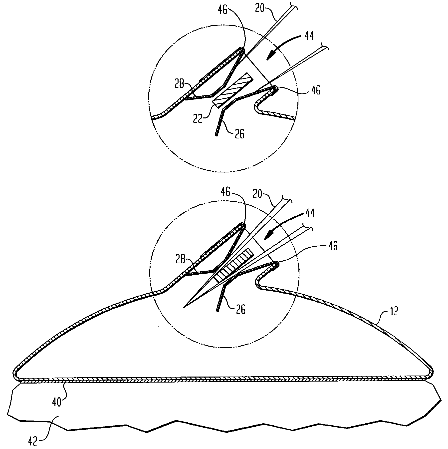
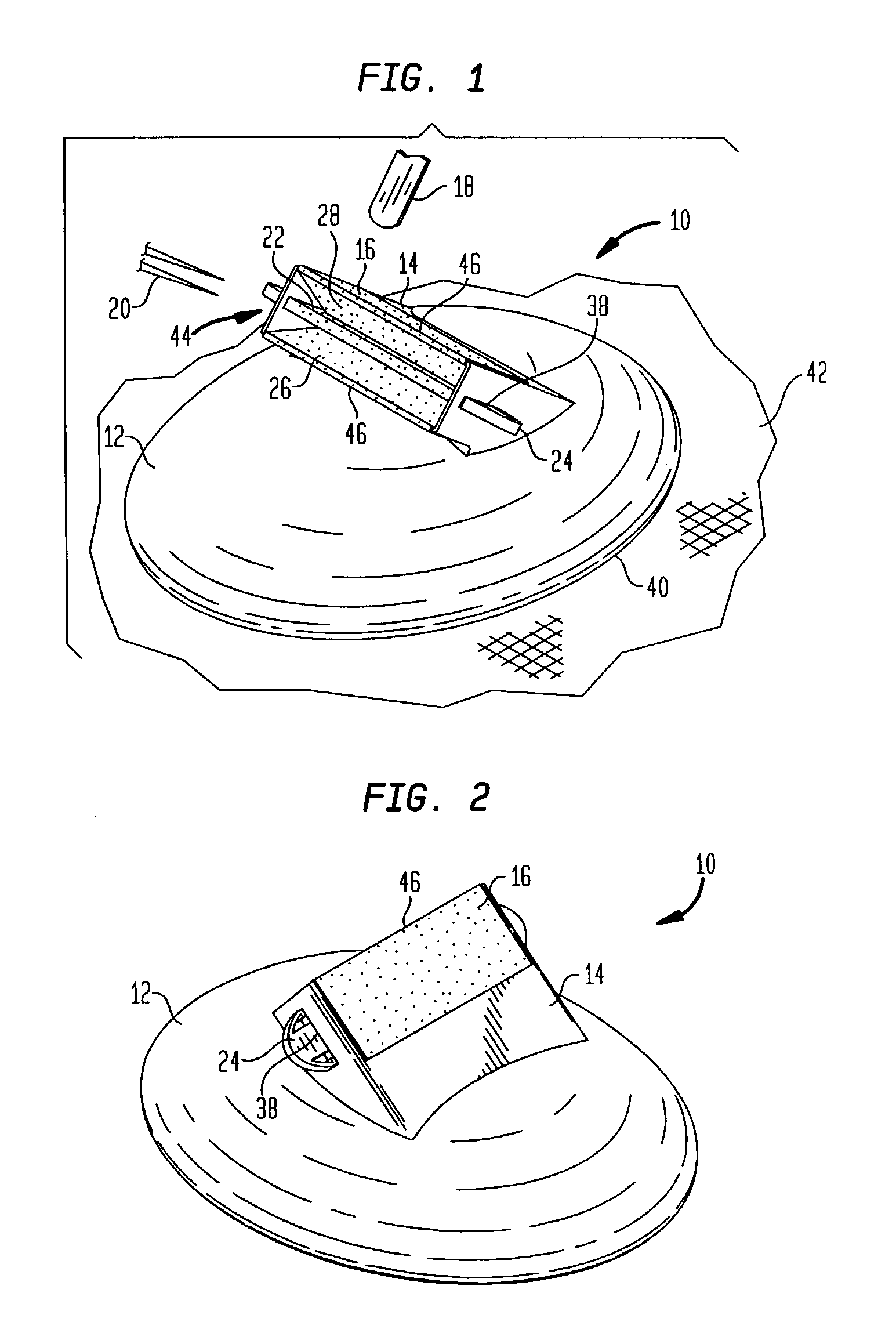
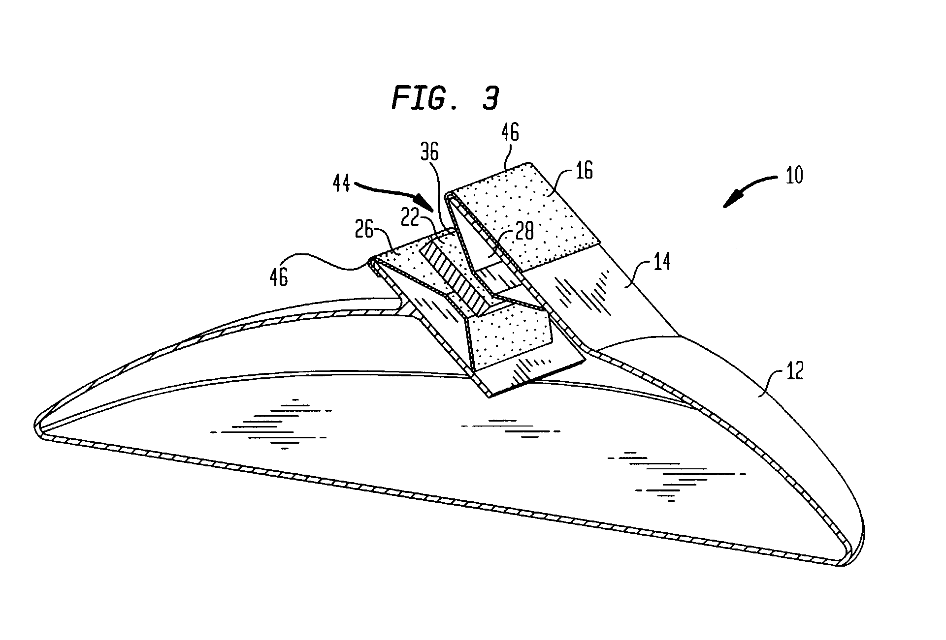
[0031]The preferred embodiment of the invention 10 is illustrated in FIG. 1. The device is attached via an adhesive undersurface 40 directly to surgical drapes 42 in the operative setting. The device base 12 is preferably constructed of rigid plastic. It houses and supports the cleaning unit 14. The latter has an external first, abrasive top surface 16 which permits easy cleaning of debris from a surgical instrument tip such as a cautery device (unipolar 18, or bipolar forceps 20). The cleaning unit 14 also houses a transverse cleaning strut 22 which supports abrasive surfaces permitting efficient debris and blood removal from the internal aspect of bipolar cautery tips 20 when the latter are rubbed and straddled across the strut 22 during entry into the cleaning unit 14. The transverse strut 22 is locked to the cleaning unit...


PUM

PropertyMeasurementUnit
angleaaaaaaaaaa
abrasiveaaaaaaaaaa
currentaaaaaaaaaa

Abstract

A fine surgical instrument tip-cleaning device including a box-like cleaning unit that provides an outer abrasive cleaning surface and internal cleaning surfaces. The internal structure of the device consists of a transverse abrasive cleaning strut, which can be straddled by instruments such as forceps or bipolar cautery tips. The sidewalls of the cleaning box also contain abrasive cleaning lateral surfaces, which approximate the central cleaning strut. The lateral surfaces have a springiness, which permits the entrance of instrument tips into the box while maintaining constant contact of the abrasive cleaning surfaces against the instrument. In this fashion, effective removal of debris, coagulate and other substances are possible from surgical instruments even from the internal surfaces of forceps-type instruments. Easy introduction into the cleaning unit and back and forth motion of an instrument provides effective cleaning of the latter.

Description

CROSS-REFERENCE TO RELATED APPLICATIONS[0001]This application claims benefit of priority U.S. Provisional Patent Application Ser. No. 60 / 374,925 filed Apr. 23, 2002 and entitled “Surgical Instrument and Electrocautery Tip-Cleaning Device”, by Frank J. Schwab the entire content and substance of which is hereby incorporated into this application in total by reference.BACKGROUND OF THE INVENTION[0002]1. Field of the Invention[0003]This invention relates to a device having multiple cleaning surfaces for safely and effectively cleaning forceps, bipolar and uni-polar cautery device tips.[0004]2. Description of the Related Art[0005]The problem of maintaining clean forceps and electrocautery device tips during surgery has persisted since the time of their development. Electrocautery devices assist the surgeon in maintaining a surgical field with limited bleeding thus limiting morbidity to the patient while also permitting safer technical performance of the procedure itself. Electrocautery d...

Claims


Application Information

Patent Timeline
Patent Type & Authority Patents(United States)
IPC IPC(8): A61B19/00B08B1/00A61B18/14
CPCA61B19/34B08B1/00A61B18/14A61B90/70
Inventor SCHWAB, FRANK J.
Owner SCHWAB FR J
Why Eureka
Try Eureka