
System, method, device and computer code product for improving the readability of an electronic compass

a technology of electronic compass and readability, applied in the field of electronic compasses, can solve the problems of electronic compasses built around 2-axis sensors, high tilt error sensitivity of electronic compasses, and possible compass reading error of 30 degrees or mor

Active Publication Date: 2005-11-15
NOKIA TECHNOLOGLES OY
View PDF8 Cites 34 Cited by
  • Summary
  • Abstract
  • Description
  • Claims
  • Application Information

AI Technical Summary

Benefits of technology

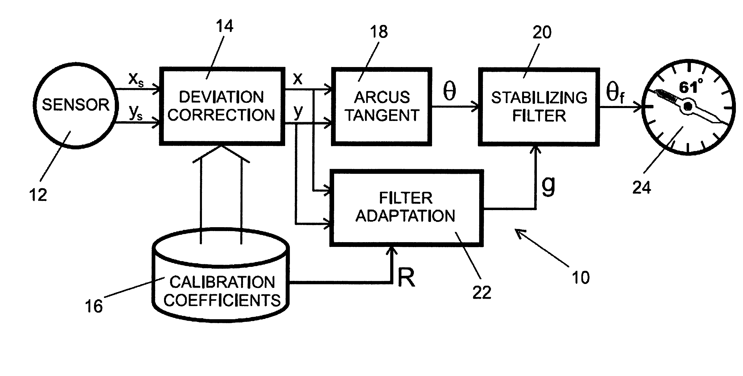
[0008]One embodiment of the invention relates to an electronic compass. The compass can include a sensor configured to measure the Earth's magnetic field and to provide sensor output signals indicative of the measured magnetic field, a stabilizing filter configured to filter out random tilt errors incorporated into the sensor output signals, and a filter adaptation module configured to control the stabilizing filter response based on the sensor ou

Problems solved by technology

Electronic compasses built around 2-axis sensors can suffer from high sensitivity to tilt errors.
If the tilt angle is not kept constant during measurements there can be error.
If the compass device is tilted say 10 degrees, a compass reading error of 30 degrees or more is possible.
Sensitivity to tilt differs between different geographical areas but can generally create problems for electronic compasses.
As this approach can be cost prohibitive, many low-end electronic compass implementations compensate for tilt error in other ways, such as through the use of a bubble level indicator.
While the bubble level indicator approach may provide a low cost solution if the user is in a stable environment, it is very difficult to use if the user is walking or otherwise moving.
Wobbling causes tilt errors that make the compass reading noisy and difficult to read.
In bad cases of wobble, the compass needle can even start spinning around.
The inexperienced user judges such a device to be of very low quality.

Method used


Image

  • System, method, device and computer code product for improving the readability of an electronic compass
  • System, method, device and computer code product for improving the readability of an electronic compass
  • System, method, device and computer code product for improving the readability of an electronic compass

Examples


Embodiment Construction

[0020]Embodiments of the current invention generally relate to readability improvements for an electronic compass through the use of a stabilizing filter and a filter adaptation module. Embodiments of the invention are able to inhibit the situation in which the compass direction indicator spins uncontrollably and stabilize the compass heading during random tilt error conditions. The implementation cost of various embodiments of the invention is practically negligible. The embodiments can be used to provide significant added value and quality boost to low end compasses as well as further improve the performance of high-end devices, which may include a tilt sensor.

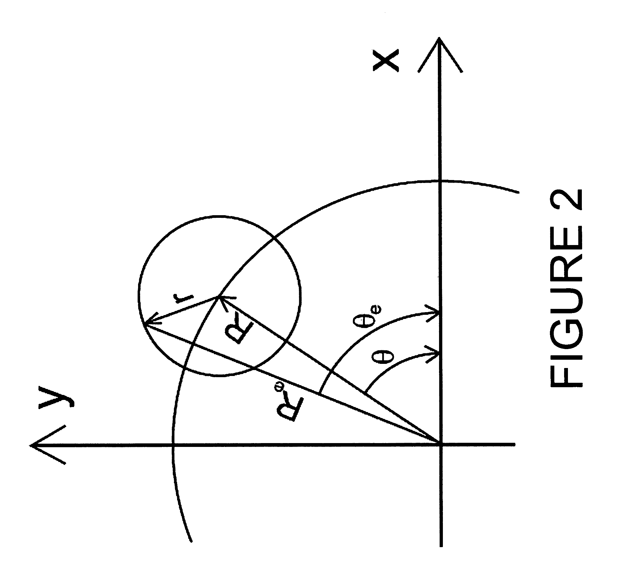
[0021]In one embodiment, to stabilize the compass reading, the stabilizing filter adapts its response to the radius error of the sensor signal. If the error gets larger, the filter response slows down and tries to retain the prior correct compass reading. If the compass wobbles around the horizontally leveled position, the r...


PUM


Abstract

A system, method, device and computer code product is disclosed for stabilizing compass heading under tilt error conditions from an uncorrected electronic compass reading. Exemplary embodiments include a stabilizing filter configured to filter out tilt errors incorporated into the uncorrected electronic compass reading and a filter adaptation module configured to control the stabilizing filter response based on the signal radius of the uncorrected compass reading and a pre-calibrated ideal radius for the compass. The filter adaptation module can be configured to calculate a filter response parameter as a function of the relative difference between the signal radius of the uncorrected compass reading and the pre-calibrated ideal radius. The filter response parameter can be passed to the stabilizing filter for controlling its operation.

Description

FIELD OF THE INVENTION[0001]The present invention relates generally to the field of electronic compasses. More particularly, the present invention relates to stabilizing filters for improving the readability of an electronic compass.BACKGROUND INFORMATION[0002]In general, compasses determine geographic orientation with reference to the Earth's magnetic field, which generally runs north and south for most populated parts of the Earth. As the magnetic poles of the Earth are not located in the same position as the Earth's geographic poles, there is an error between the geographic (true) and magnetic (compass) headings, which is called variation. Variation is location and time dependent. Conventional compasses employ a freely movable, magnetically sensitive member which aligns itself with the Earth's magnetic field and points towards the Earth's magnetic north pole.[0003]Electronic compasses, on the other hand, determine geographic orientation without using a magnetically sensitive memb...

Claims


Application Information

Patent Timeline
IPC IPC(8): G01C17/38G01C17/00G01C17/28
CPCG01C17/28G01C17/38
Inventor AHOLA, TOM MIKAEL
Owner NOKIA TECHNOLOGLES OY
Learn More