Dual check-relief valve

a double check and valve body technology, applied in the direction of fluid couplings, functional valve types, couplings, etc., can solve the problems of high manufacturing process costs and time-consuming process

Inactive Publication Date: 2005-11-15
SAUER DANFOSS NORDBERG
View PDF9 Cites 8 Cited by
  • Summary
  • Abstract
  • Description
  • Claims
  • Application Information

AI Technical Summary

Benefits of technology

[0010]The present invention is a check relief valve that provides the functionality of dual check relief valves. The check relief valve has a first and second poppet that is operably connected to a spring within a guide. The first and second poppet are disposed within a first seat and second seat respectfully. The dual check valve has three separate fluid passages, one in fluid communication with the high pressure line of the hydrostatic circuit, the second in fluid communication with the low pressure side of the hydrostatic circuit, and one in fluid communication with the charge pressure line within the hydrostatic circuit. By being fluidly connected to all three of the fluid lines in the hydrostatic circuit the check valve of the present invention is able to use a spring and poppet design to route fluid through the circuit as desired, thus accomplishing the functionality of two separate check relief valves.

Problems solved by technology

Though a two valve system is effective in allowing a hydrostatic circuit to function, the manufacturing of two separate valves can cause great cost in the manufacturing process of the valves.
Furthermore, because one must machine two different valves in the manufacturing process, this process can take a lot of time.

Method used


Image

  • Dual check-relief valve
  • Dual check-relief valve
  • Dual check-relief valve

Examples


Embodiment Construction

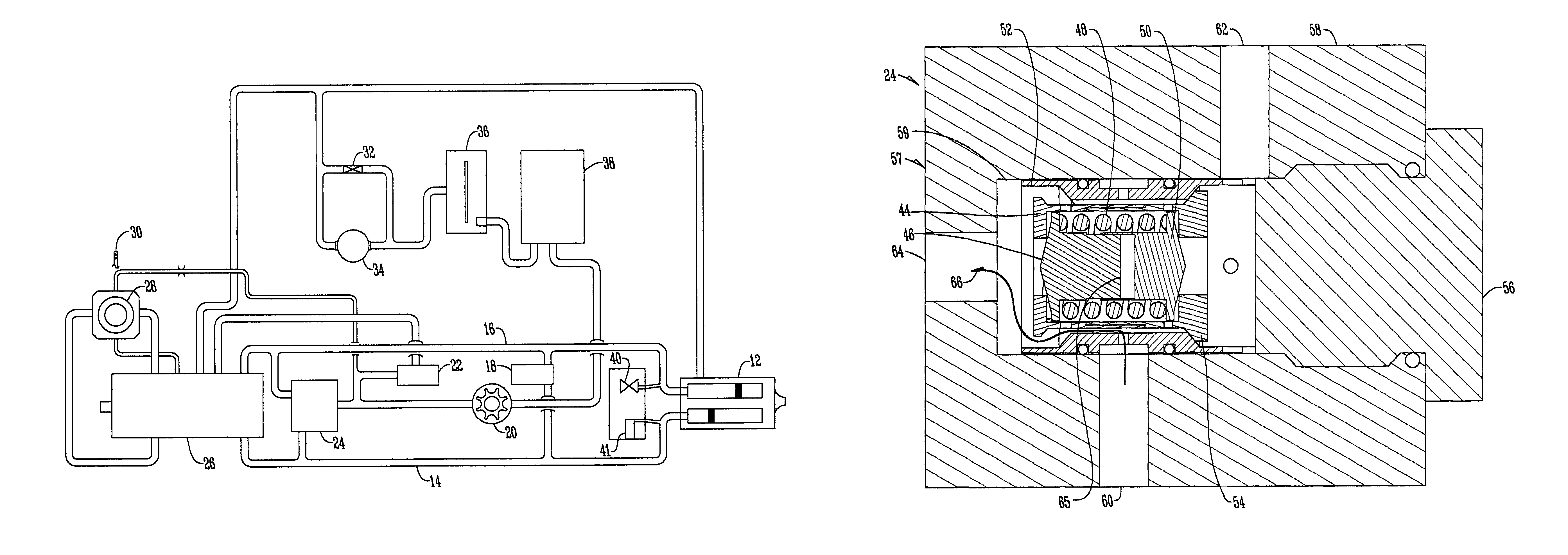
[0016]FIG. 1 shows a typical hydrostatic circuit 10 having a motor 12 that provides fluid to a high pressure fluid line 14 and a low pressure fluid line 16 wherein bypass valve 18 determines which side of the hydrostatic circuit has the low or high pressure. The hydrostatic circuit 10 also has a charge pump 20 that sends fluid to a charge relief valve 22 and a dual check and high pressure valve 24. The dual check and high pressure relief valve also receives fluid from the high and low pressure lines 14 and 16 respectfully. Fluid from the high and low pressure lines 14 and 16 flows into a pump 26 that is fluidly connected to displacement control valve 28 that is controlled by control handle 30. Also, within the circuit is a heat exchanger bypass 32, a heat exchanger 34, a reservoir 36, and a filter 38. The hydrostatic circuit 10 may also have a charge pressure relief valve 40 or loop flushing module 41.

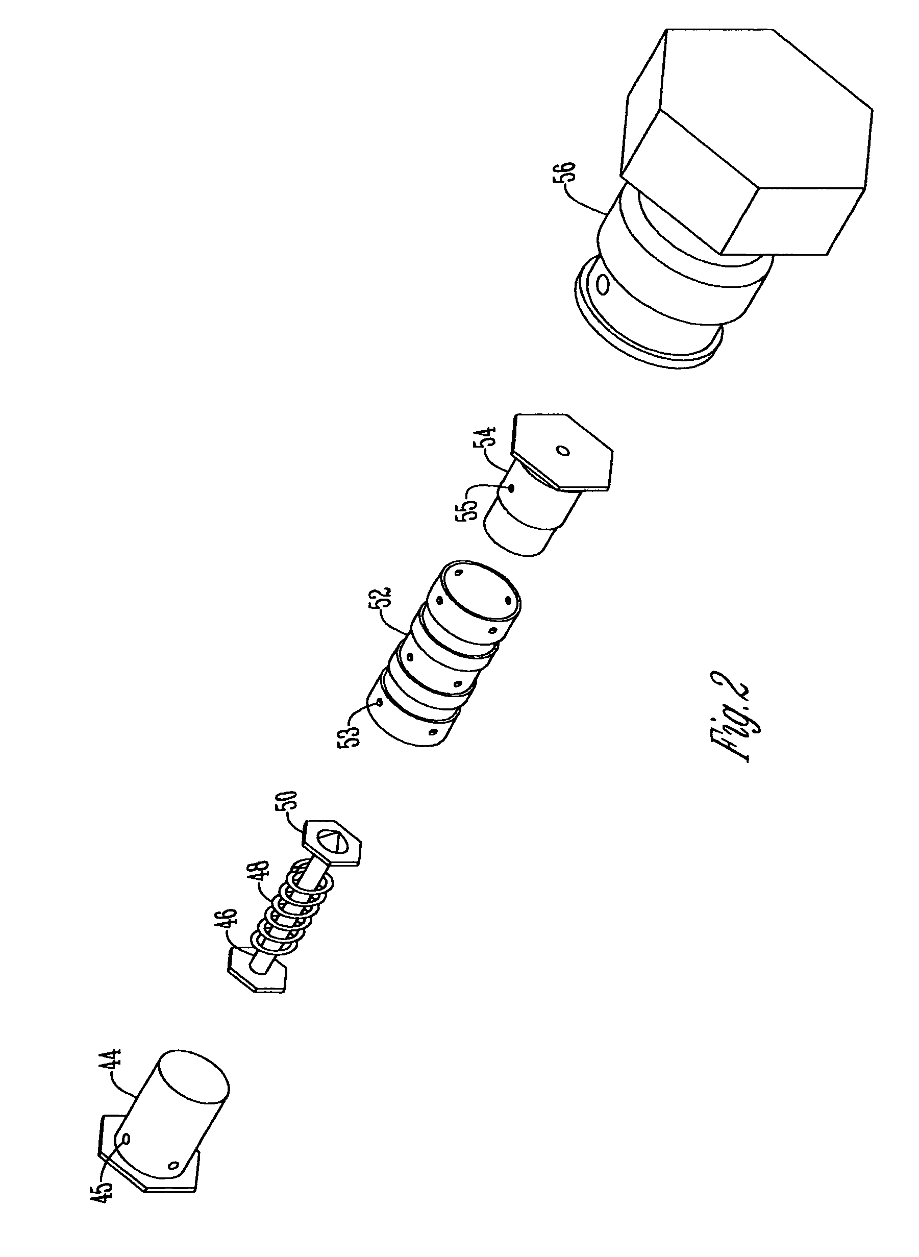
[0017]The dual check and high pressure relief valve 24 has valve components that a...


PUM


Abstract

A dual check and high pressure relief valve that is able to perform the function of a hydrostatic high pressure relief valve and a check valve. The new valve has two poppets separated by a spring that are within two seats within a guide and secured by a plug. By adjusting the seats the relief pressure setting is set. The dual check and high pressure relief valve has three separate passageways that allow fluid flow between different combinations of the passages depending upon the function desired within the hydrostatic circuit. A dashpot is also included between the two poppets to provide positive dampening of the system.

Description

BACKGROUND OF THE INVENTION[0001]This invention relates to a dual check relief valve for a hydrostatic circuit. Typical hydrostatic circuits use two check relief valves; the first is closed and will act as a high pressure relief valve if the high pressure side of the hydrostatic circuit exceeds the valve setting. The second check relief valve has the check valve open to allow charge flow into the pump. When the pump is stroked to reverse flow, the first check relief valve will open to allow charge flow into the pump and the second check relief will close and operate as a high pressure relief valve.[0002]Though a two valve system is effective in allowing a hydrostatic circuit to function, the manufacturing of two separate valves can cause great cost in the manufacturing process of the valves. Furthermore, because one must machine two different valves in the manufacturing process, this process can take a lot of time. Therefore, it is desired in the art to have a single valve that is a...

Claims


Application Information

Patent Timeline
Patent Type & Authority Patents(United States)
IPC IPC(8): F16D31/02F16K17/24F16H61/40F16H61/4017
CPCF16D31/02F16H61/4017
Inventor LANDHUIS, KEVIN J.
Owner SAUER DANFOSS NORDBERG
Why Eureka
Try Eureka