Noise reducing combustor

a combustion chamber and noise reduction technology, applied in the direction of machines/engines, mechanical equipment, lighting and heating apparatus, etc., can solve the problems of not teaching or suggesting the use of a similar or modified combustion chamber wall construction, and the noise produced by gas turbine engines is largely caused

Active Publication Date: 2005-11-15
PRATT & WHITNEY CANADA CORP
View PDF20 Cites 65 Cited by
  • Summary
  • Abstract
  • Description
  • Claims
  • Application Information

AI Technical Summary

Benefits of technology

[0010]There is further provided, in accordance with the present invention, a method of attenuating selected audible frequencies passing through a gas turbine engine combustor having spaced-apart inner and outer walls, the method comprising the steps of: selecting an area in said outer wall and locating at least an impingement aperture therein; and selecting an area in said inner wall corresponding to said area in

Problems solved by technology

Noise produced by gas turbine engines is largely caused by pressure and acoustic vibrations which can occur in and around the combustion chamber under certain conditions.
However, few have enabled the reduction of noise generated by the combustion chamber of such a g

Method used


Image

  • Noise reducing combustor
  • Noise reducing combustor
  • Noise reducing combustor

Examples


first embodiment

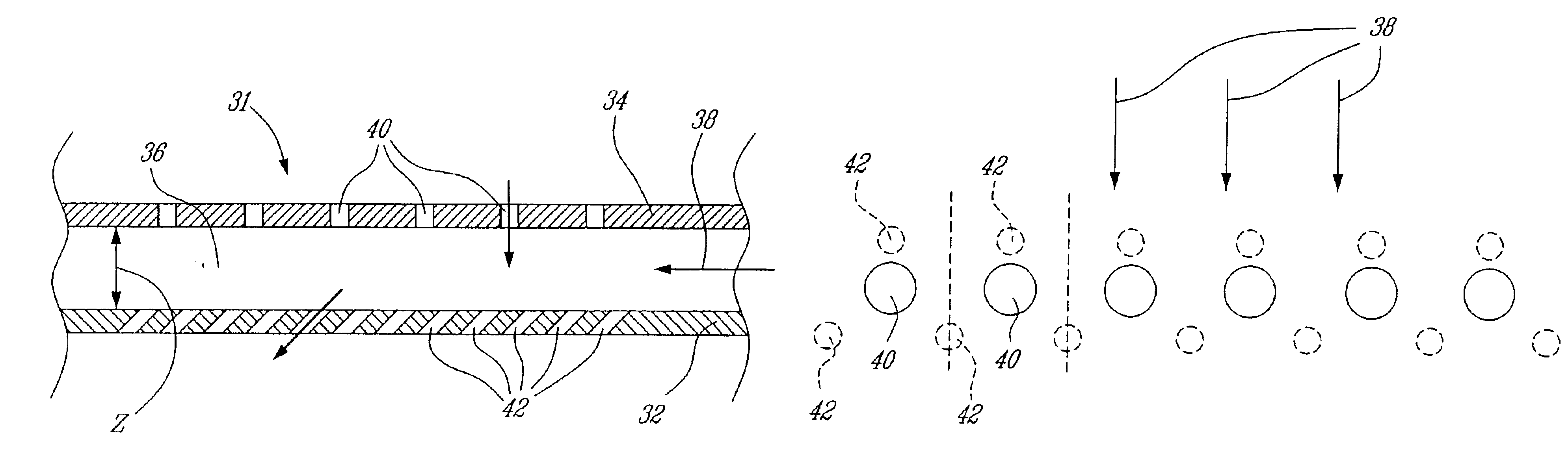
[0027]Referring to FIGS. 4a and 4b, the relative arrangement of impingement apertures 40 and effusion apertures 42 is clearly seen. Particularly, a group of 3 effusion apertures 42 is disposed relative to each impingement aperture 40. The effusion apertures 42 in each group are preferably equally spaced from one another, being arranged at vertices of an equilateral triangle defined by the effusion apertures 42. The impingement aperture 40 is preferably disposed with each such triangular group of effusion apertures 42, being positioned closest to the effusion aperture 42 that is located most upstream relative to the direction of flow 38 through the cavity 36 of the combustor double-wall 31. The effusion apertures 42 of each group are spaced apart in a stream-wise direction, substantially parallel to the direction of flow 38, by a distance x, and in the span-wise direction, substantially perpendicular to the direction of flow 38, by a distance y. The impingement apertures 40 are space...

second embodiment

[0029]Referring now to the alternate arrangement of impingement apertures 40 and effusion apertures 42 in the second embodiment FIG. 5, in which the ratio of the number of effusion apertures 42 to the number of impingement apertures 40 is 2:1. Particularly, a group of 3 effusion apertures 42 is disposed relative to each impingement aperture 40, but each group of effusion apertures 42 shares two effusion apertures 42 with opposed adjacent groups. Therefore, each impingement aperture 40 is disposed downstream, relative to a direction of fluid flow 38 in the cavity 36, of an effusion aperture 42, and two effusion apertures 42, each shared with an adjacent group on either side of the impingement aperture 40, are disposed downstream again therefrom. As such, for each impingement aperture 40 in this embodiment there is one whole and two “half”, or shared, effusion apertures 42, and thereby a ratio of the number of effusion apertures 42 to the number of impingement apertures 40 of 2:1.

third embodiment

[0030]Referring to the alternate arrangement of impingement apertures 40 and effusion apertures 42 in the third embodiment FIG. 6, in which the ratio of the number of effusion apertures 42 to the number of impingement apertures 40 is 4:1. In this embodiment, each impingement aperture 10 is positioned substantially at a center of a group of four effusion apertures 42, disposed at vertices of a square oriented such that the centers of two effusion apertures 42 are coincident with a stream-wise axis 46 passing through the center of the impingement aperture 40, and two effusion apertures 42 are coincident with a span-wise axis 48 passing through the center of the impingement aperture 40. The span-wise and stream-wise directions are relative to a direction of fluid flow 38 through the cavity 36 between the inner effusion wall 32 and the outer impingement wall 34 of the combustor double-wall 31. Such groups of four effusion apertures 42 are repeated an equal span-wise distance from one an...


PUM


Abstract

A gas turbine engine combustor defining a combustion zone therein and being adapted for receiving compressed air from a compressor. The combustor comprises inner and outer walls spaced-apart by a predetermined spacing distance and defines a cavity therebetween. The outer wall has a first area defining at least an impingement aperture therein, the impingement aperture permits fluid flow communication between the compressor and the cavity. The inner wall has a second area corresponding to the first area and defines a plurality of effusion apertures therein, the effusion apertures permitting fluid flow communication between the cavity and the combustion zone, and each of the effusion aperture defines a cross-sectional area smaller than that of the impingement aperture. The effusion apertures are disposed in groups having a predetermined geometric arrangement relative to the impingement aperture and define a ratio of number of effusion apertures to the impingement aperture of between about 2:1 and about 4:1. The combustor thereby provides damping of audible frequencies less that about 1600 Hz passing therethrough.

Description

TECHNICAL FIELD[0001]The present invention relates generally to gas turbine engines, and particularly to a gas turbine combustion chamber providing reduced noise levels.BACKGROUND OF THE INVENTION[0002]Noise produced by gas turbine engines is largely caused by pressure and acoustic vibrations which can occur in and around the combustion chamber under certain conditions. Many advancements have been made to reduce the overall noise levels generated by gas turbine engines. However, few have enabled the reduction of noise generated by the combustion chamber of such a gas turbine engine, such that the far field noise level caused by such powerplants is reduced. Such vibrations can be damped by providing fluid mechanic means which influence the flow of hot combustion gasses sufficiently to completely prevent, or at least significantly suppress, the excitation of acoustic vibrations. Helmholtz resonators have also been employed as damping elements to eliminate undesirable vibrations, which...

Claims


Application Information

Patent Timeline
IPC IPC(8): F23M20/00F23R3/00
CPCF23R3/002F23R3/54F23R2900/00014F23R2900/03041F23R2900/03044F23M20/005Y02T50/60
Inventor ALKABIE, HISHAM
Owner PRATT & WHITNEY CANADA CORP
Why Eureka
Try Eureka