Floating barrel handgun method of recoil elimination

a floating barrel and handgun technology, applied in the field of firearms, can solve the problems of difficult automatic manipulation of ablative gaskets in mechanical ways, the danger of behind the gun, and the danger of personnel nearby, and achieve the effect of ensuring safety

Inactive Publication Date: 2005-11-15
LAVIN WALTER M
View PDF19 Cites 13 Cited by
  • Summary
  • Abstract
  • Description
  • Claims
  • Application Information

AI Technical Summary

Benefits of technology

[0011]The first invention in the floating barrel design relates to a mechanical means for automatically venting the diverted propellant gas which, upon firing, is accumulated in the forward chamber of the gun. The gas is not vented from the chamber through the external barrel to the outside environment, but rather is discharged through longitudinal nozzles or passageway voids cut through the metal body of the annulus of the internal barrel. The gas is vented in a rearward direction through the floating barrel annulus voids into the firing chamber after the projectile has left the gun. The firing chamber is enclosed by the external barrel which makes the venting much safer.
[0013]When the gas from the forward chamber is discharged through the voids, the gas pressure of the vented gas streams are high and the gas of the streams further expands in the bore of the of the external barrel. With the bore of the external barrel functioning as a divergent nozzle, the velocity of the gas increases from an already high velocity and an additional force is created on the base of the floating barrel, including the closed bore of the barrel, and this force works to push the gun forward. As this gas escapes the gun through the hollow spaces in the rear of the external barrel, some of the kinetic energy of the gas is transferred to the rear structures of the gun forcing it in a rearward direction, but the design of the gun can be made to minimize this energy transfer.
[0016]In some conventional handguns, the breech block is held in place within the gun in order to maintain firing chamber pressure until the projectile exits, then the breech block is unlocked from the receiver and made to move rearward to perform one or more self actuating functions. A modification of a short recoil process for unlocking the breech block from the external barrel when applied to the floating barrel design would not only facilitate the performance of self-actuating functions, but would also aid in increasing the efficiency of the propellant gas venting from the passageway voids since the vented jet streams of gas move through the floating barrel annulus and are directed toward the breech block. With a breech block moving rearward away from the gas streams, less kinetic energy is transferred from the gas streams to the rear of the gun.

Problems solved by technology

However, as with the preliminary floating barrel design, expelling gas at a high velocity in a rearward direction into the environment created a zone behind the gun which could be very hazardous to personnel nearby and precluded the use of the gun as a close-carry weapon.
This ablative gasket was difficult to automatically manipulate in a mechanical way in repositioning the internal barrel for multiple firings.

Method used


Image

  • Floating barrel handgun method of recoil elimination
  • Floating barrel handgun method of recoil elimination
  • Floating barrel handgun method of recoil elimination

Examples


Embodiment Construction

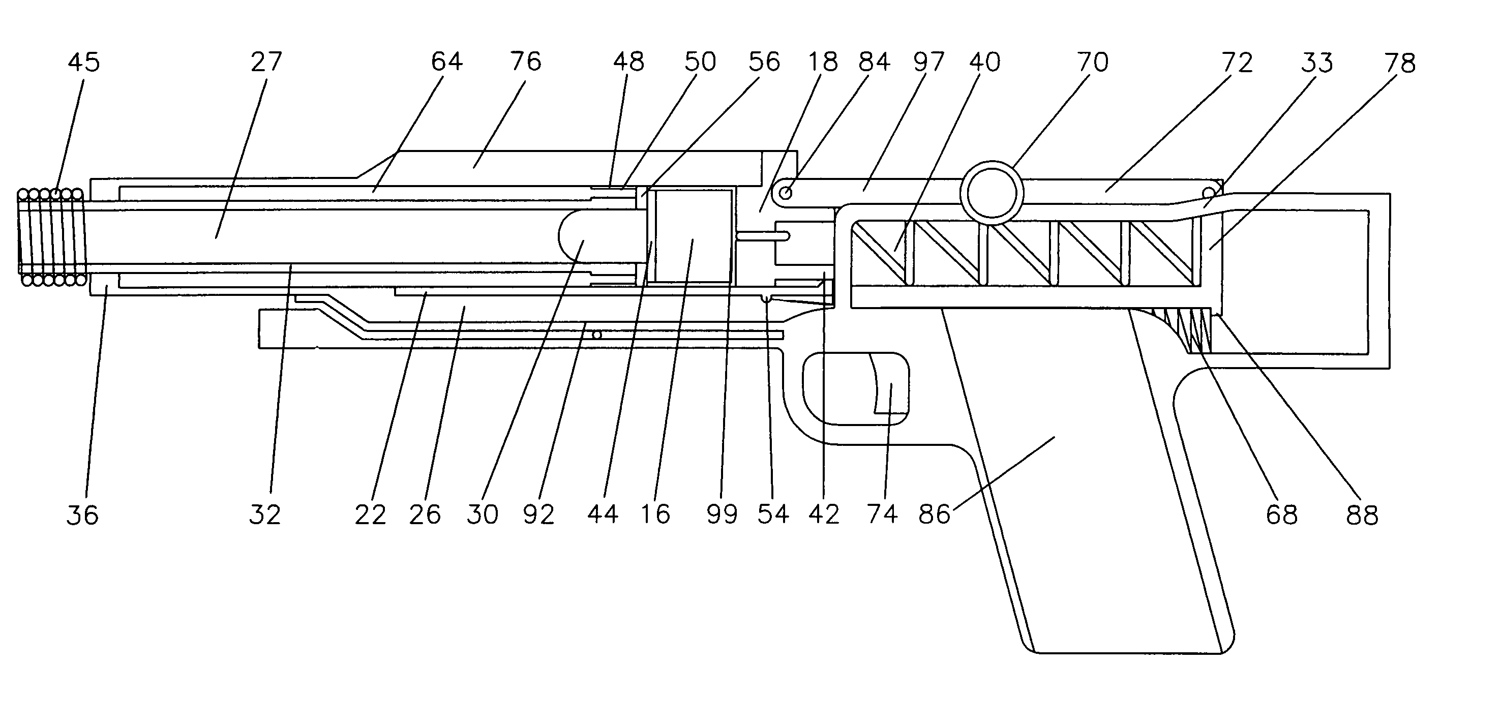
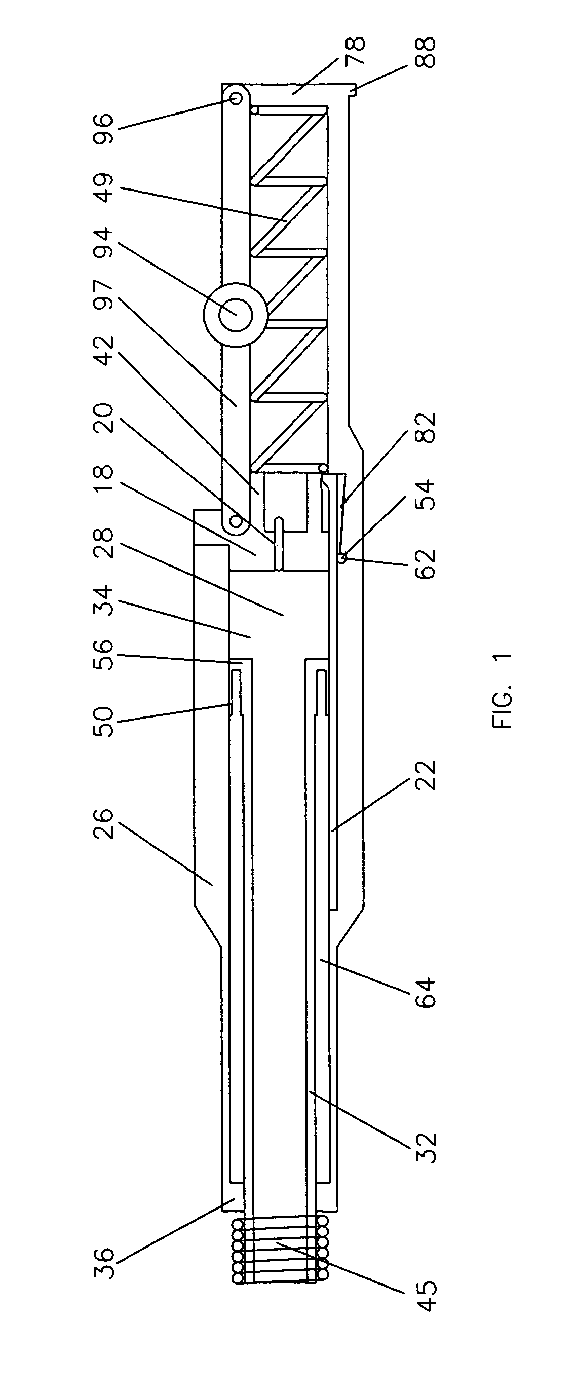
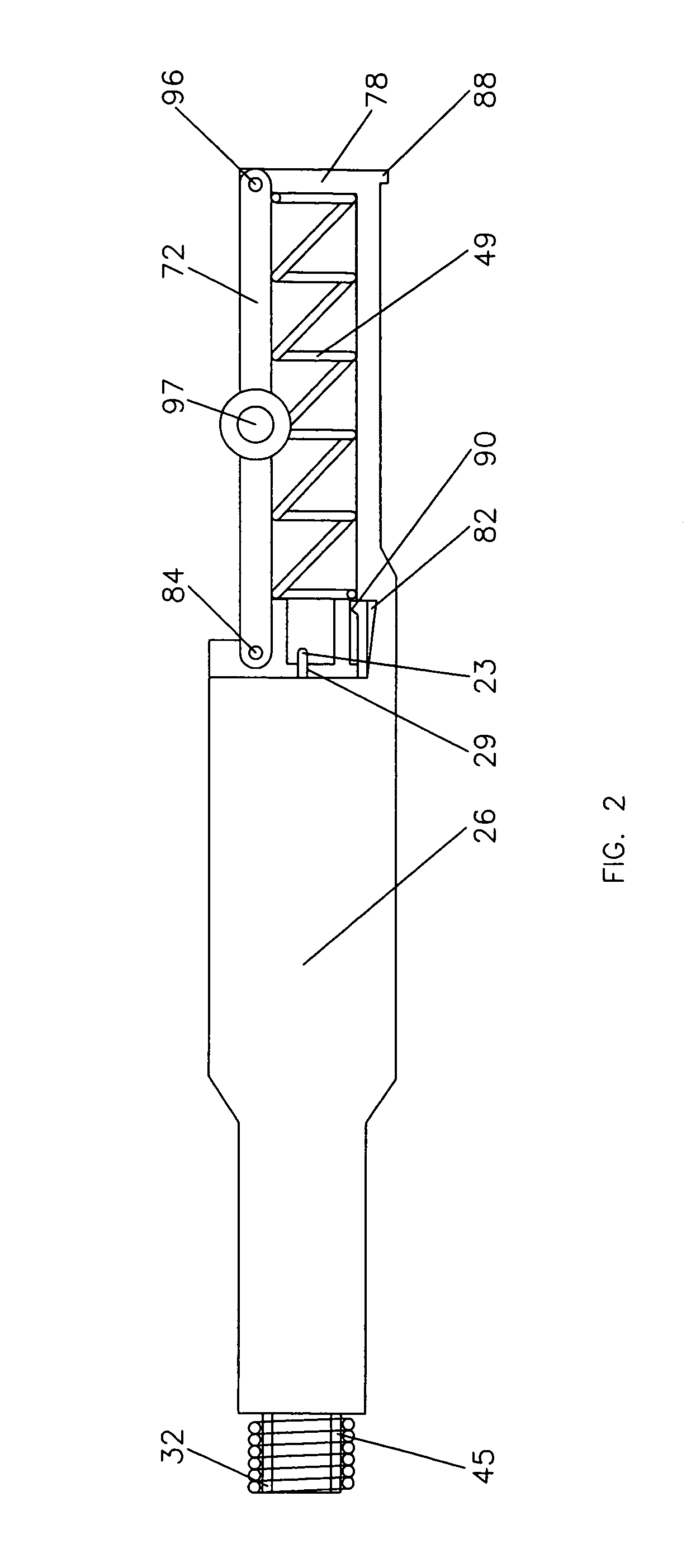
[0037]The firing mechanism of the gun comprises a forwardly biased longitudinal firing pin (23) slidably mounted in a tubular aperture (29) centrally located in breech block (18). The gun is actuated by manual retraction of trigger (74) causing hammer (80) positioned in handle (86) to move against the action of a spring [not shown]. Hammer (80) (FIG. 6) rises from location in handle (86), moving through an opening in a sliding plate or cradle (92), an opening in external barrel (26) and an opening in the rear of breech block (18), (openings not shown), striking rear end of firing pin (23). Hammer (80) is positioned in handle (86) of gun beneath firing pin (23) to eliminate the need for a long or inertial type firing pin (23).

[0038]Trigger (74) is operated by trigger assembly (not shown). Trigger assembly forms no part of subject invention and trigger assemblies comprising a spring, sear and notch are well known in the art and may be positioned in handle (86) so that when trigger (74...


PUM


Abstract

A floating barrel gun design, a design in which a propellant gas discharge is used to counterbalance the recoil force of the gun, has been improved to include a novel automatic mechanical mechanism which allows the floating or inner barrel to be held stationary within the gun while the gas is discharged and after the discharge is complete, the barrel is released to return to its pre-actuation position. The discharge of gas is also made safer by an automatic mechanical mechanism for venting the accumulated gas, and this mechanism is activated as the projectile leaves the gun. The mechanism requires that the gas be discharged into the interior of the gun and the recoil-countering gas streams be directed toward a rearward moving breech block. The gas is discharged automatically during the firing cycle, as the firing chamber pressure falls upon the projectile exit, by venting the compressed gas through passageway nozzles which proceed through the annulus of the floating barrel and are controlled by rotatable metal plates. The discharged gas ultimately exits the gun through spaces in the outer barrel which open to the gas as the breech block moves rearward. To explain the invention, the operating of a handgun is described as the preferred embodiment. The handgun is a result of an integration of the ideas concerning a floating barrel delivery system with conventional ballistic designs.

Description

[0001]This invention uses a telescoping or floating barrel delivering system of my invention U.S. Pat. No. 6,490,959 B2 granted 2002 Dec. 10.BACKGROUND OF THE INVENTION[0002]This invention relates, in general, to a gun and in particular to a gun which uses a telescoping or floating barrel as part of a propellant gas discharge design used to eliminate the gun's recoil.[0003]The floating barrel gun design of U.S. Pat. No. 6,490,959 B2 offered certain advantages over state of the art gun technology. Conventional recoilless guns, using propellant gas discharge to neutralize recoil, were developed in England and Germany during World War II and were used as battlefield artillery weapons. These guns eliminated recoil by discharging propellant gas from nozzles located behind the breech block into the environment in high velocity gas streams as the projectile was accelerated through the barrel. The floating barrel design, by transferring and compressing, before expelling the gas, offered a g...

Claims


Application Information

Patent Timeline
Patent Type & Authority Patents(United States)
IPC IPC(8): F41A9/00F41A9/61F41A3/00F41A3/50F41A5/16F41A21/48
CPCF41A3/50F41A5/16F41A21/48
Inventor LAVIN, WALTER M
Owner LAVIN WALTER M
Why Eureka
Try Eureka