Key array structure

a key array and array technology, applied in contact mechanisms, emergency protective devices, printing, etc., can solve the problems of uneven gap formation, only accurate positioning of long holes, and inability to accurately position long holes, so as to prevent the key from being elastically deformed, avoid dimension errors, and boost the stable positioning of key members

Inactive Publication Date: 2005-11-15
LITE ON IT
View PDF3 Cites 39 Cited by
  • Summary
  • Abstract
  • Description
  • Claims
  • Application Information

AI Technical Summary

Benefits of technology

[0008]A key array structure according to the present invention is characterized in that each two adjacent key members are connected through an elastic element; the elastic element can be functioned as a buffer under a circumstance that a key array is caused to deform slightly when the key array is manufactured by injection forming so as to adjust properly a distance error formed between the position hole disposed in each key member and the corresponding position pin in the relative member caused from the deformation owing to the control of manufacturing conditions to allow the positioning hole in each key array structure according to the present invention to be able to be precisely positioned with the corresponding positioning pin.
[0010]Along hole type auxiliary positioning hole can further disposed in a fixing rack of a key array structure according to the present invention besides a positioning hole so as to boost the stable positioning for the key member. For avoiding the dimension error caused from the heat participated in the manufacturing of the key array, the auxiliary positioning hole is designed to be a long hole type to tolerate the error.
[0011]A projecting post is disposed on the opposite of the key main body on each key seat in a key array structure according to the present invention is used to prop against a IC plate to prevent the key from being elastically deformed after frequent and numerous pressings.
[0012]For further preventing the key from being elastically deformed after numerous pressings, a projecting post can also be disposed at a proper position on the elastic element mentioned above besides the projecting post is disposed on the key seat and the opposite side of key main body to assist the fixation of the key and prevention of the elastic deformation.
[0014]Besides, a guide notch is disposed on the key seat at a side of the key seat below or above the key main body or both of them in the key array structure according to the present invention. The guide groove is corresponding to the raised mass on the relative member so as to be engaged with the raised mass to prevent the key from heeling.

Problems solved by technology

However, only an precise positioning hole shown as an element 11 in FIG. 1 is disposed in an key array structure for a general positioning design thereof, and this precise positioning hole is usually in the middle of the key array and the rest of positioning holes are long holes shown as an element number 12 in FIG. 1; the long hole positioning is only an auxiliary but not accurate positioning.
The deviation of the positioning hole is possibly caused from a manufacturing error when the key array is manufactured or a paint such as pigment or a metal layer needed to coat or plate on the key array for increasing artistic quality or product value and a baking process needs to be practiced thereon at this time.
The accumulations of the error on the manufacturing of the key array mentioned above and the tolerance mentioned above causes the deviation of the key so that a uneven gap could formed between it and the positioning hole.

Method used


Image

  • Key array structure
  • Key array structure
  • Key array structure

Examples


Embodiment Construction

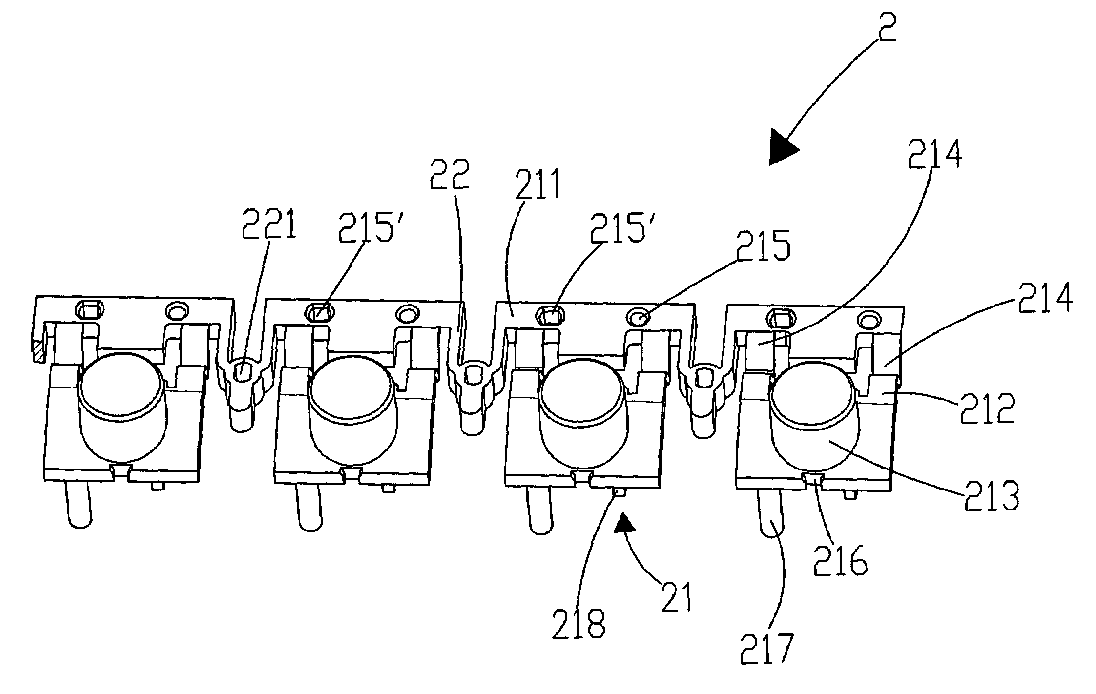
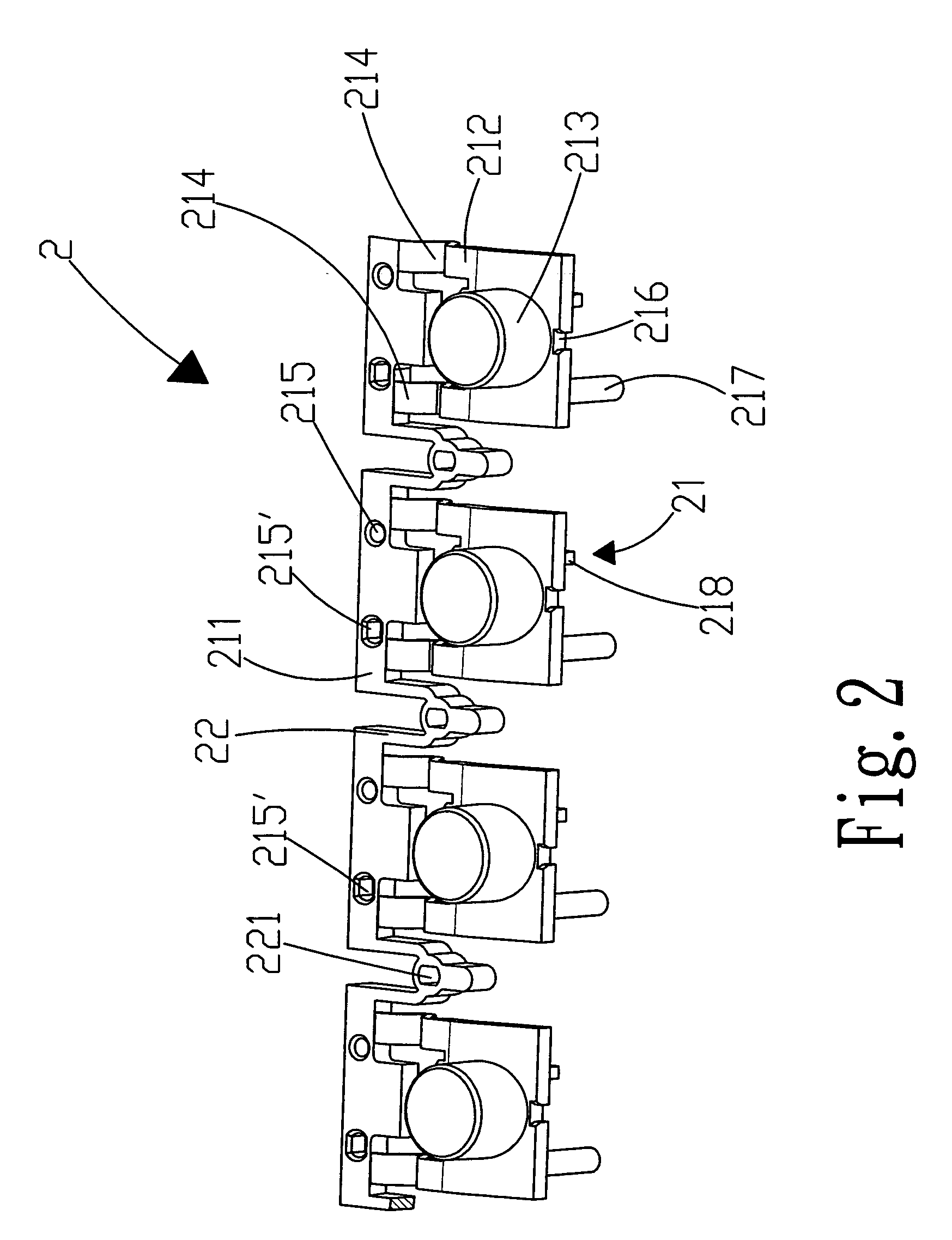
[0024]Please refer to FIG. 2. FIG. 2 is a front schematic view, showing a key array structure of a preferred embodiment according to the present invention. For clarity in description, a positioning hole and an auxiliary positioning hole are disposed in each key member in the figure. A key array 2 is constituted by a plurality of key members 21 and an elastic element 22 connected between each two adjacent key members, in which the key member comprises a fixing rack 211, key seat 212 and key main body 213, in which each key member is connected to the fixing rack through two elastic arms 214 and to provide an elastic force to press down or rebound the key main body 213 owing to the deformation of the elastic arms 214 when the key main body 213 is pressed, a positioning hole 215 and auxiliary hole 215′, a guide notch 216 is disposed on the key seat 212 approximately in the middle of a side of the key seat 212 below the key main body 213 and a projecting post 217 and pressing element 218...


PUM


Abstract

A key array structure comprises a key array constituted by connecting a plurality of key members arranged in an array, it is characterized in that an elastic element is connected between each two adjacent key members and a positioning hole or position holes is or are disposed in the key member. The elastic member disposed between each two adjacent key members of the key array structure according to the present invention has a cushioning effect to adjust the deformation of the key array caused from the processes such as heat baking while manufacturing so as to allow the positioning hole in each key member to be precisely positioned with a corresponding position pin on a relative member.

Description

[0001]This Non-provisional application claims priority under 35 U.S.C. § 119(a) on Patent Application No(s). 093208129 filed in Taiwan, Republic of China on May 24, 2004, the entire contents of which are hereby incorporated by reference.BACKGROUND OF THE INVENTION[0002]1. Field of the Invention[0003]The present invention relates to a key array structure, and more particularly to a key array in which an elastic member is disposed between each two keys to adjust the deformation yielded from manufacturing process such as hot baking to allow a positioning hole on each key member to be able to be accurately coupled with a positioning pin on a relative member.[0004]2. Description of Related Art[0005]Function keys used on electronic machines such as a video recorder / player, CD player and DVD recorder / player are always designed to be a function key array structure for being matched up with the model and the outlook of such facilities. These keys are assembled one by one in the earlier time....

Claims


Application Information

Patent Timeline
Patent Type & Authority Patents(United States)
IPC IPC(8): B41J5/00B41J5/08G06F3/02H01H13/7057
CPCH01H13/7057H01H2229/034H01H2229/064H01H2233/004
Inventor LU, MING HSING
Owner LITE ON IT
Why Eureka
Try Eureka