Cable strain-relief member for a PC fan

a strain-relief member and pc fan technology, applied in the direction of coupling device connection, electrical apparatus, cooling/ventilation/heating modification, etc., can solve the problems of user usage troubles, the binding method and the fixture structure according to the prior art cannot meet the requirements of the user on actual usag

Inactive Publication Date: 2005-11-15
DATECH TECH CO LTD
View PDF5 Cites 2 Cited by
  • Summary
  • Abstract
  • Description
  • Claims
  • Application Information

AI Technical Summary

Benefits of technology

[0006]Therefore, the main purpose of the present invention is that, by setting a strain-relief member at a rib of a fan frame, lead wires can be firmly bound at the rib of the fan frame so that the lead wires will not be swung left and right, or be shaken up and down, to be loosened by an external force.
[0007]Another purpose of the present invention is that the strain-relief member can be released according to the actual need for easy maintenance and packing of the fan.
[0008]To achieve the above purposes, the present invention is a cable strain-relief member for a PC fan, comprising a pressing part, two locking parts at both ends of the pressing part and two releasing parts at the two joint portions between the pressing part and the locking parts. So, the present invention can be set at a rib of a fan frame to bind lead wires at the rib of the fan frame to prevent from being swung left and right, or being shaken up and down, to be loosened by an external force. Besides, the strain-relief member can be released according to the actual need for easy maintenance and packing of the fan.

Problems solved by technology

And, because the constriction bond 33 can not be easily released after being tightened, a user is not able to release the constriction bond 33 on maintenance or packing, which causes trouble on usage.
So, the binding method and the fixture structure according to the prior arts can not fulfill the requirements from the user on actual usage.

Method used


Image

  • Cable strain-relief member for a PC fan
  • Cable strain-relief member for a PC fan
  • Cable strain-relief member for a PC fan

Examples


Embodiment Construction

[0019]The following descriptions of the preferred embodiments are provided to understand the features and the structures of the present invention.

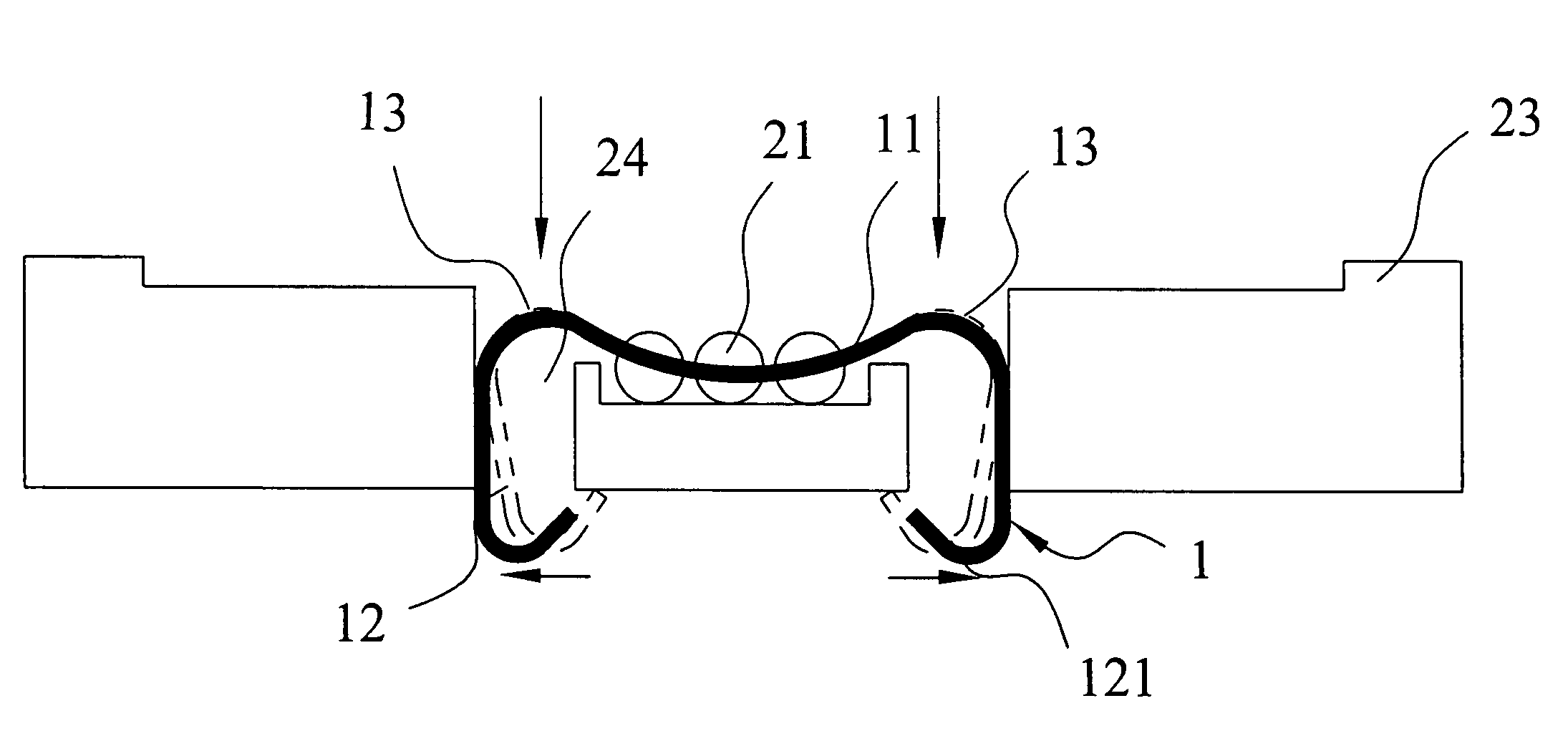
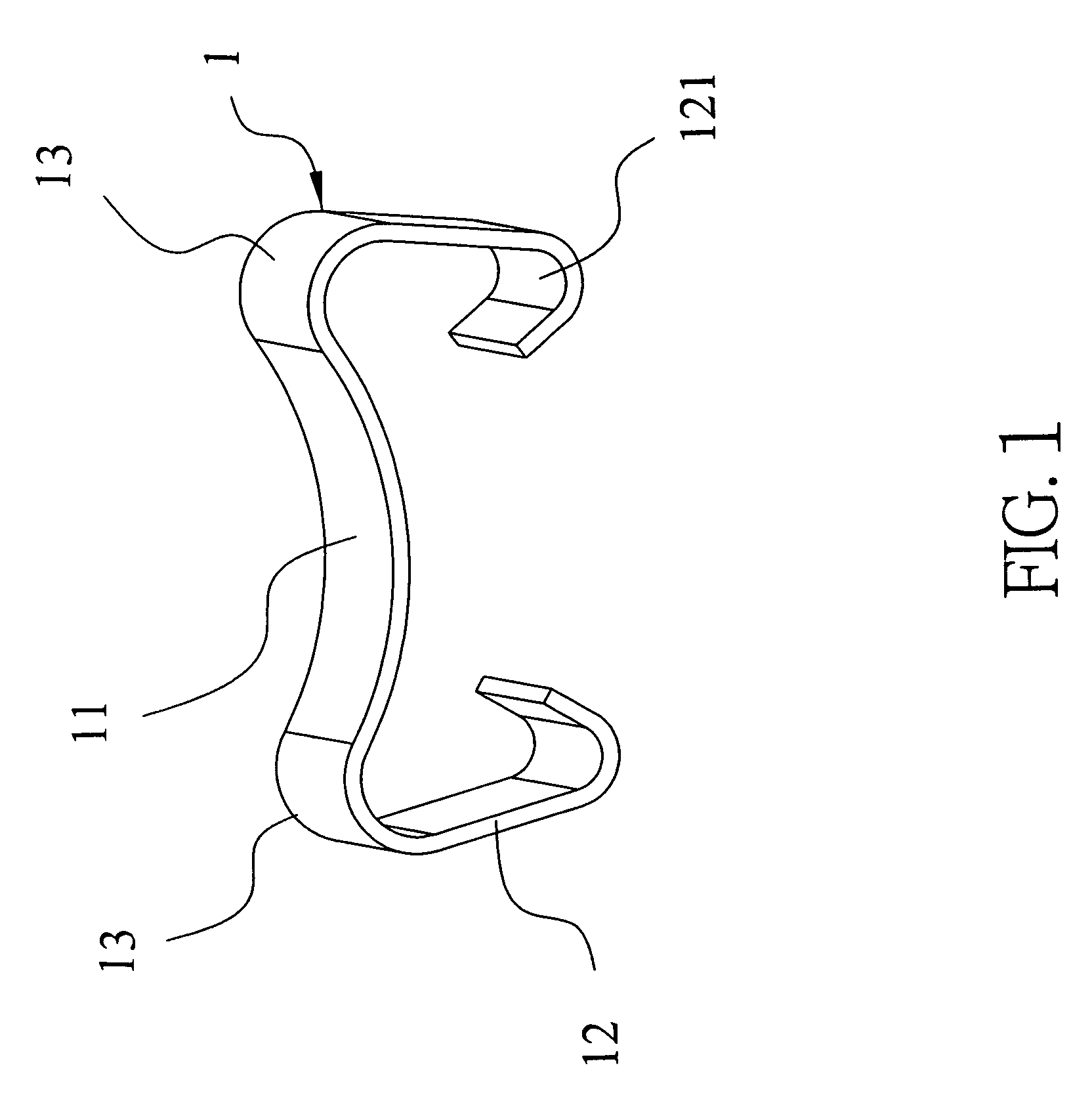
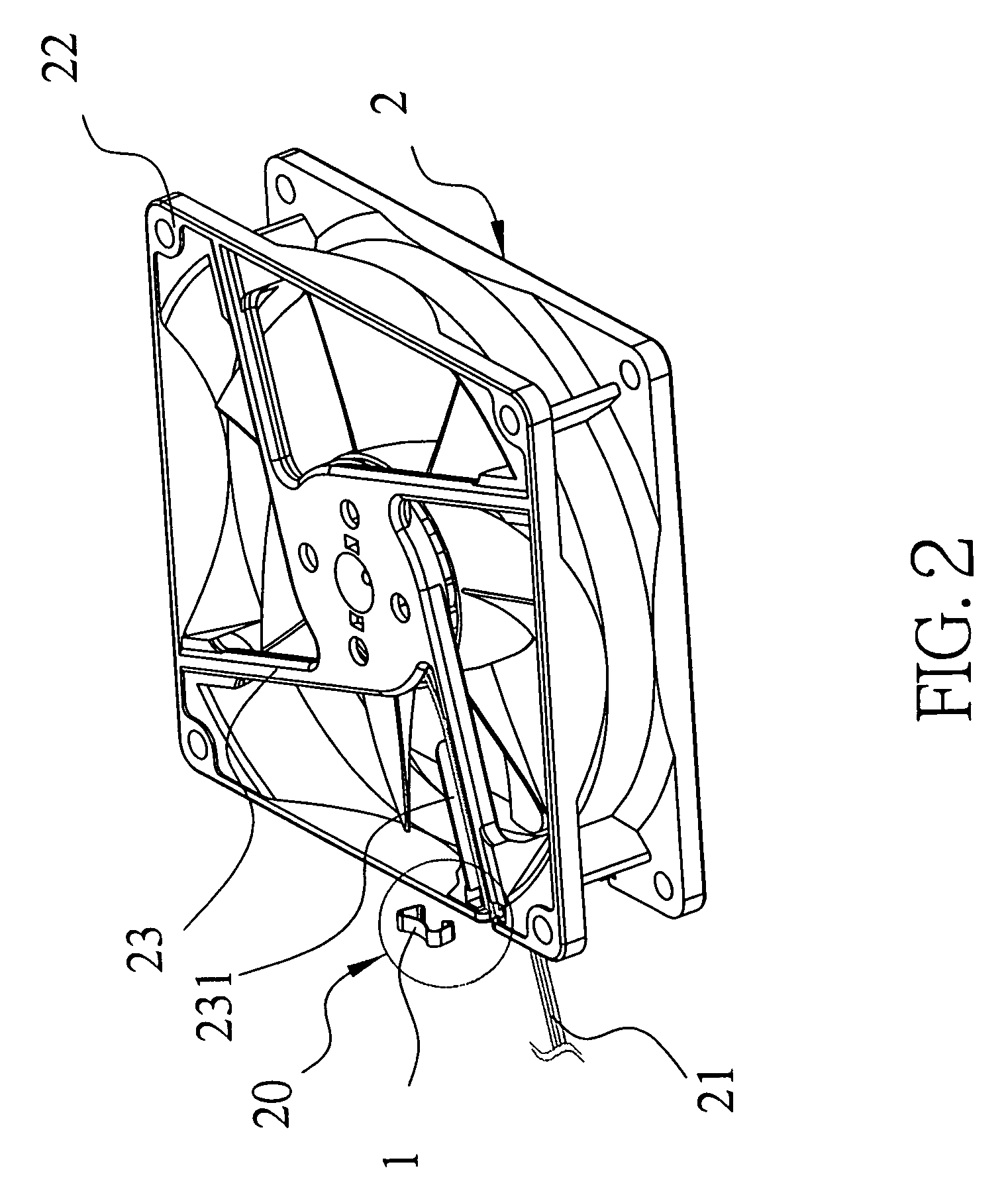
[0020]Please refer to FIG. 1, which is a perspective view according to the present invention. As shown in the figure, the present invention is a cable strain-relief member for a PC fan, comprising a pressing part 11, two locking parts 12 and two releasing parts 13, formed as an integral whole. The present invention can be set at a rib of a fan frame to firmly bind lead wires of the circuit board of the fan so that the lead wires of the circuit board can be limited at the rib of the fan frame to prevent from being swung left and right, or being shaken up and down, to be loosened by an external force. Besides, the strain-relief member 1 can be released for easy maintenance and packing of the fan according to the actual need.

[0021]The pressing part 11 mentioned above comprises a cambered surface.

[0022]The two locking parts 12 are at both ends...


PUM


Abstract

The present invention is to provide a cable strain-relief member for a PC fan, comprising a pressing part, two locking parts at both ends of the pressing part, and two releasing parts at the two joint portions between the pressing part and the locking parts. Accordingly, the strain-relief member can be set at a rib of the fan frame to firmly bind lead wires on the rib of the fan frame to prevent from being swung left and right, or being shaken up and down, to be loosened by an external force. Besides, the strain-relief member can be released for easy maintenance and packing of the fan according to the actual need.

Description

FIELD OF THE INVENTION[0001]The present invention relates to a strain-relief member. More particularly, the present invention relates to a strain-relief member which firmly binds lead wires of a circuit board at a rib of a fan frame to prevent from being swung left and right, or being shaken up and down, to be loosened by an external force. Besides, the strain-relief member can be released according to the actual need for easy maintenance and packing of the fan.DESCRIPTION OF THE RELATED ARTS[0002]As is known, the binding method for lead wires of a circuit board of a fan according to the prior art, as shown in FIG. 5, is done by guiding the lead wires 32 to a rib 31 of the fan frame 3 and putting it in a fillister 34 of the rib 31. Then, the lead wires 32 and the rib 31 are bound by a constriction bond 33 to establish the lead wires 32 at the rib 31.[0003]The above method according to the prior art can establish the lead wires 32 at the rib 31. But, because the constriction bond 33 ...

Claims


Application Information

Patent Timeline
Patent Type & Authority Patents(United States)
IPC IPC(8): H01R13/58H05K7/20
CPCH05K7/20172
Inventor LI, NIEN-LUNLIU, CHIH-KUANLIN, HSU-JUNGHO, PING-TSANG
Owner DATECH TECH CO LTD
Why Eureka
Try Eureka