Capacitance sensor

a technology of capacitive sensors and capacitive sensors, applied in the direction of resistance/reactance/impedence, measurement devices, instruments, etc., can solve the problems of failure of detection, the device mentioned above, and the inability to dispose of the device in the vicinity of an electromagnetic valv

Inactive Publication Date: 2005-11-15
UNIREC +1
View PDF14 Cites 6 Cited by
  • Summary
  • Abstract
  • Description
  • Claims
  • Application Information

AI Technical Summary

Benefits of technology

[0010]According to the first aspect, a variation of capacitance of the path in the piping can be detected by a measuring electrode and a grounding electrode of the conductive metallic film wound in turns. Therefore, a fluid state of a fluid substance in the path can be surely and easily decided, and sanitary conditions in the path also be maintained.
[0012]Accordingly, a decision can surely be made of a fluid state in a piping, for example, such as on a normality or abnormality or of a change of kind of fluid substance. Moreover, the fluid state of the fluid substance flowing through the path in a piping can be decided with non-contact manner, securing a sanitary condition even if the fluid substance is a food. The fluid state of the fluid substance flowing in the path can be decided by capacitance or its variation, with large voltage variation without needing an integration of detected values, and with a reduced calculation amount. The fluid state is detected by capacitance or its variation, so that it hardly receives influences of a magnetic field. Even if the fluid substance includes a plurality of solid bodies such as metal, soil, or stone and is formed a solid fluid substance such as a metallic flow, soil flow, or stone flow, electrodes are kept from collision with the fluid substance. Therefore, the fluid state of the fluid substance including a plurality of solid bodies can be surely and easily decided.

Problems solved by technology

The device mentioned above, however, has some problems.
The detection of conductivity tends to be influenced by an associated magnetic field, as the result it is impossible to dispose the device in a vicinity of an electromagnetic valve.
This causes the electrodes 103 and 105 to be damaged, and a failure of detection.

Method used


Image

  • Capacitance sensor
  • Capacitance sensor
  • Capacitance sensor

Examples


Embodiment Construction

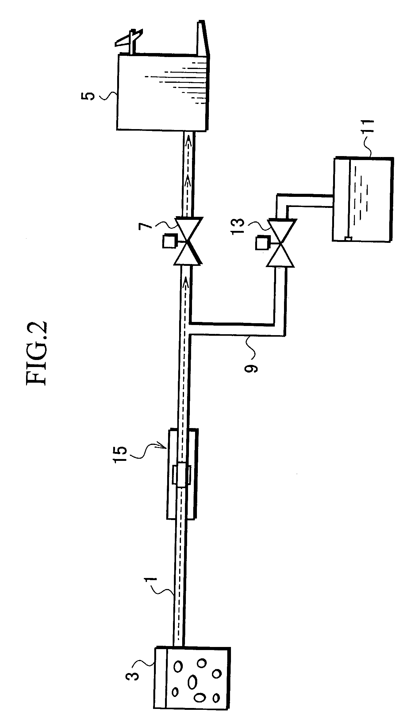
[0025]FIG. 2 is a schematic constitutional diagram of a piping fluid control system applying a capacitance sensor according to an embodiment of the present invention. According to this embodiment, a piping 1 is adapted as illustrated to conduct a fluid substance, for example beer, to be sent through an inside path thereof.

[0026]The piping 1 is connected at one end thereof to a beer tank 3, and at the other end to a beer take-out machine 5 serving as a substance take-out machine. On the way to the beer take-out machine 5 end of the piping 1 is provided with a first electromagnetic open-close valve 7, which is an adjust means as a first open-close valve to be interposed between a position of the substance take-out machine and a position of a later described capacitance sensor. The first electromagnetic open-close valve 7 allows controlling a fluid state of beer as a fluid substance flowing the path in the piping 1. That is, when the first electromagnetic open-close valve 7 is opened, ...


PUM

PropertyMeasurementUnit
capacitanceaaaaaaaaaa
conductiveaaaaaaaaaa
conductivityaaaaaaaaaa

Abstract

To detect a variation of capacitance in a path of a piping and enable to decide a fluid state of a fluid substance flowing through the path in the piping, a capacitance sensor (15) includes a measuring electrode (33) and a grounding electrode (35) made of a conductive metallic film and wound around a path in the piping (1), with an insulator (17) in between. A shield member (23) covers the measuring electrode and grounding electrode, with an insulator in between. The grounding electrode is narrower than the measuring electrode, and the measuring electrode and the grounding electrode are alternately disposed and are wound to be spiral along a flow direction.

Description

BACKGROUND OF THE INVENTION[0001]1. Field of the Invention[0002]The present invention relates to a capacitance sensor.[0003]2. Description of the Related Art[0004]A piping fluid decision device decides a fluid state of the fluid in a piping for sending fluid. An example of the piping fluid decision device, as shown in FIG. 1, includes a piping 101 for sending fluid, electrodes 103 and 105 inserted in the piping 101. The device is arranged at, for example, a beer factory or food shop, and decides a fluid state of beer as fluid. The device detects a conductivity in the piping 101 using the electrodes 103 and 105, and detects a difference of conductivity between a liquid part 109 and a froth part 111 of the beer 107; as a result, the device decides the fluid state of the beer 107 flowing in the piping 101. Depending on a result of the deciding, the froth part 111 of the beer 107 flowing in the piping 101 is wasted, as necessary, to surely take out the liquid part 109 of the beer 107.[0...

Claims


Application Information

Patent Timeline
Patent Type & Authority Patents(United States)
IPC IPC(8): G01N27/22
CPCG01N27/226
Inventor YAMAGISHI, JUNICHIYO, EIKOU
Owner UNIREC
Why Eureka
Try Eureka