Measuring camera attitude

a technology of camera attitude and sensor, applied in the field of camera attitude sensor system, can solve the problems of floor to sag or wobble, and prior systems that only use pattern recognition not robust enough to account, and achieve the effect of enhancing video

Inactive Publication Date: 2005-11-15
SPORTSMEDIA TECH CORP
View PDF58 Cites 70 Cited by
  • Summary
  • Abstract
  • Description
  • Claims
  • Application Information

AI Technical Summary

Problems solved by technology

It has been found that prior systems that only use pattern recognition have not been robust enough to account for rapid movement of the camera during the event and may be too slow for live events.
Certain situations beyond the broadcaster's control can interfere with and be a source of error when measuring camera attitude information.
As a heavy camera is panned and tilted, the weight distribution of the camera and / or operator may cause the floor to sag or wobble.
A camera operator moving at the camera location may also cause the floor to sag or wobble.
Additionally, during an event, the tripod holding the camera can be kicked or moved.
Additionally, mechanical compliance of the various parts of the tripod and mount can also hinder an accurate camera attitude reading.

Method used


Image

  • Measuring camera attitude
  • Measuring camera attitude
  • Measuring camera attitude

Examples


Embodiment Construction

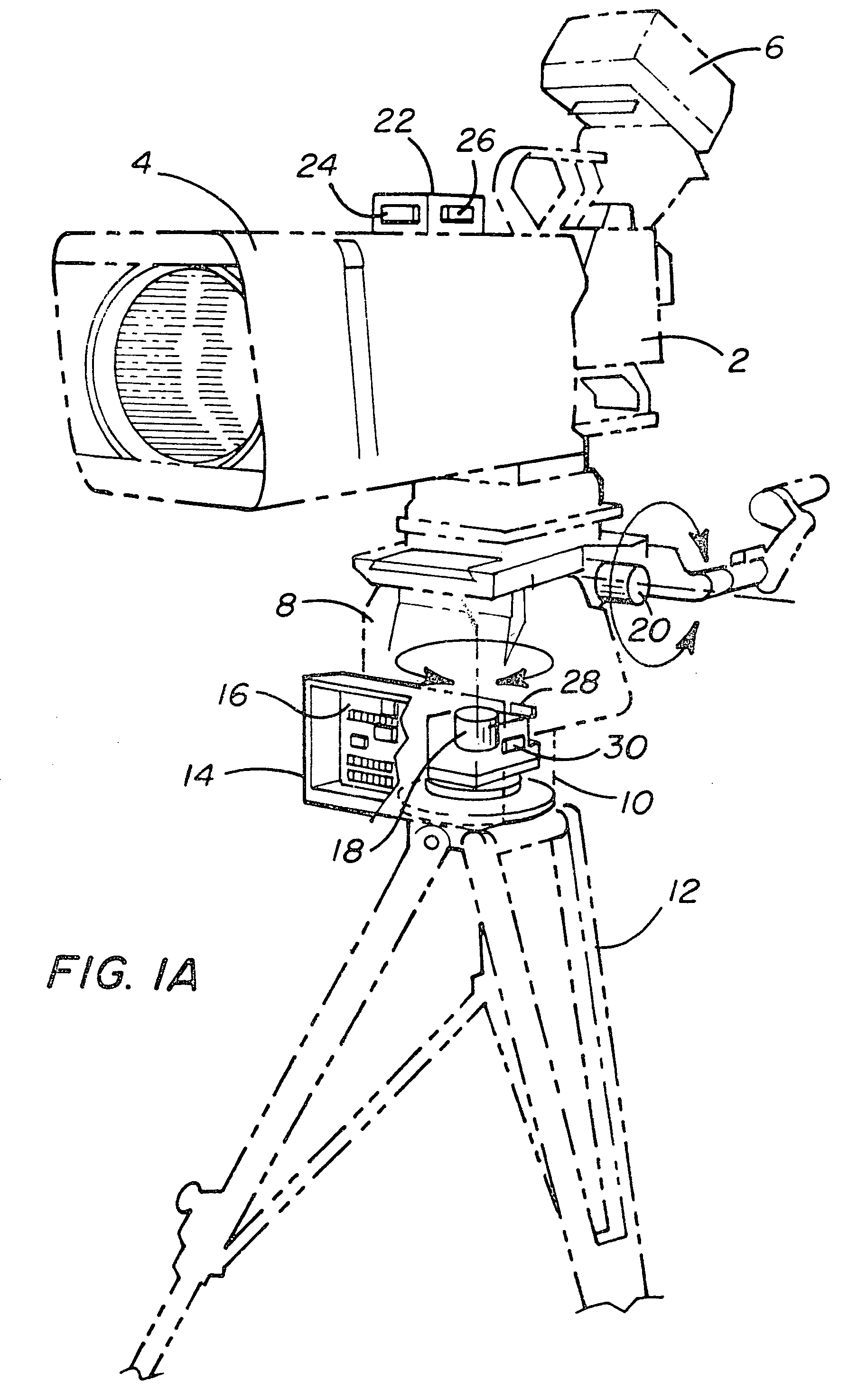
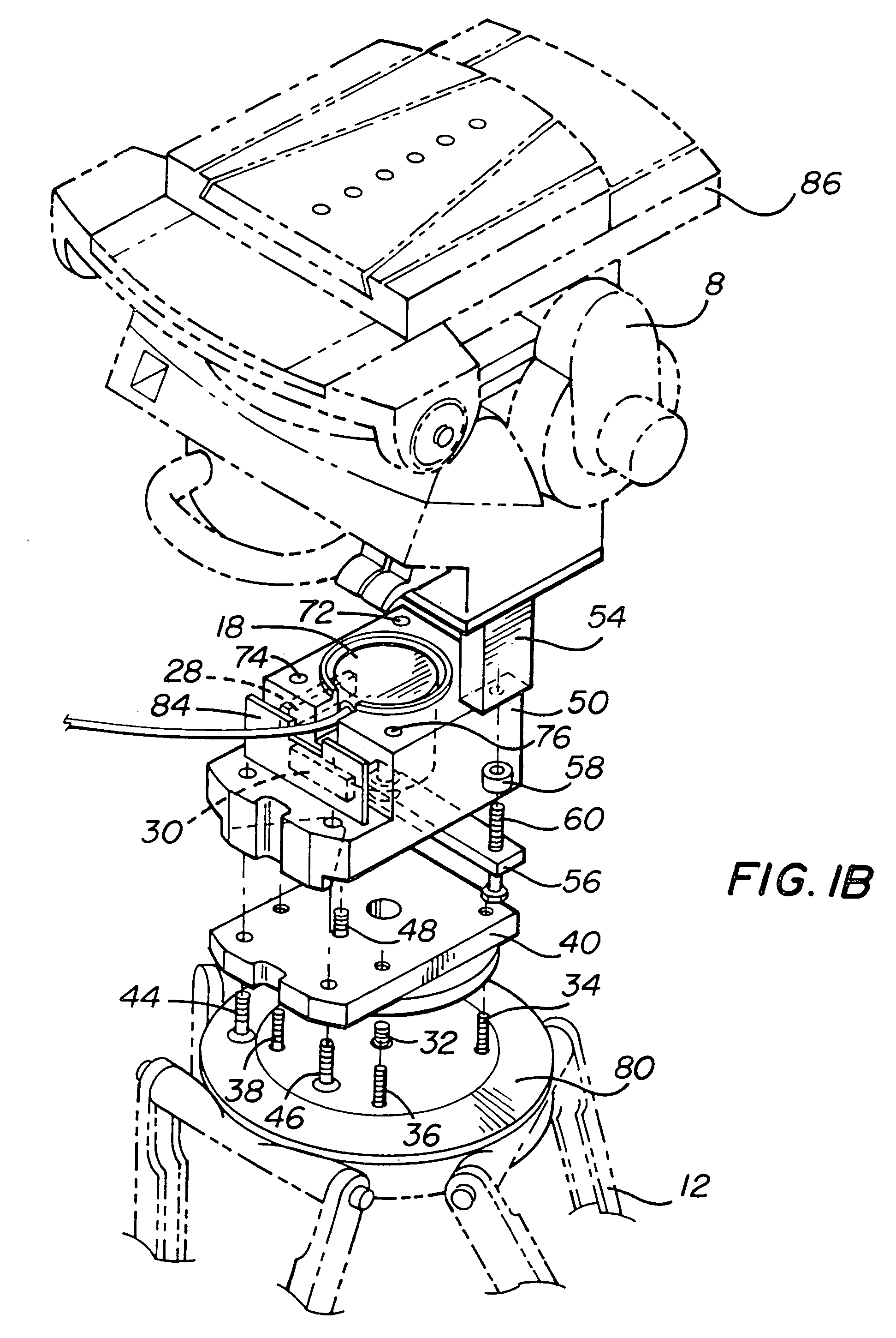
[0029]FIG. 1A shows a camera mounted on a tripod, using the sensors of the present invention. Specifically, FIG. 1A shows camera 2 with lens 4 and viewing monitor 6. Camera 2 is mounted on tripod head 8. Tripod head 8 (also called a pan-tilt head) is mounted on tripod head interface 10, which is mounted on tripod 12. Tripod head 8 allows camera 2, lens 4 and monitor 6 (collectively referred to as “camera”) to pan and tilt. One example of a suitable tripod head is the Vector 70 from Vinten, Inc. Although it is called a “tripod head,” tripod head 8 need not be used with a tripod. The term tripod head is used to describe an apparatus that allows a camera to change its orientation (e.g. pan and tilt). Tripod head interface 10 is mounted between tripod head 8 and tripod 12, and includes some of the sensors and electronics of the present invention. For example, shown in FIG. 1A inside tripod head interface 10 are pan encoder 18, inclinometer 28 and inclinometer 30. Mounted to the outside ...


PUM


Abstract

A system is disclosed for using camera attitude sensors with a camera. A camera assembly includes a tripod base, a tripod head interface mounted on the tripod base, a tripod head mounted on the tripod head interface and a camera mounted on the tripod head. The tripod head enables the camera to pan and tilt. The system also includes a first optical encoder for detecting the amount that the camera has been panned and a second optical encoder for detecting the amount that the camera has been tilted. Two inclinometers are mounted on the tripod head interface to measure attitude of the tripod head. Two gyroscopes (“gyros”) are mounted on the camera assembly. Data from the encoders, gyros and inclinometers are packaged and sent to graphics production equipment to be used for enhancing video captured by the camera.

Description

CLAIM OF PRIORITY[0001]This Application claims the benefit of U.S. Provisional Application No. 60 / 166,725, Measuring Camera Attitude, filed on Nov. 22, 1999. That Provisional Application is incorporated herein by reference.BACKGROUND OF THE INVENTION[0002]1. Field of the Invention[0003]The present invention is directed to a system for using camera attitude sensors.[0004]2. Description of the Related Art[0005]The remarkable, often astonishing, physical skills and feats of great athletes draw millions of people every day to follow sports. In particular, the number of people watching sports on television and the amount of advertising revenue received for televised sports has increased significantly. To satisfy the increased demand for televised sports, broadcasters have deployed a varied repertoire of technologies to highlight these exciting events for viewers. For example, broadcasters have started adding graphical enhancements to the video of the sporting events. Examples of graphic ...

Claims


Application Information

Patent Timeline
Patent Type & Authority Patents(United States)
IPC IPC(8): G03B17/00H04N5/228H04N5/222H04N5/262H04N5/28
CPCH04N5/222H04N5/262H04N5/28H04N5/2723Y10T74/1218
Inventor HONEY, STANLEY K.CAVALLARO, RICHARD H.WHITE, MARVIN S.O'BRIEN, TERENCE J.LAZAR, MATTHEW T.NEUBARTH, STUART K.PHILLIPS, ALAN C.MILNES, KENNETH A.
Owner SPORTSMEDIA TECH CORP
Why Eureka
Try Eureka