Increased temporal flexibility when performing/applying/reverting calibration for a printer output device

a technology of printer output device and temporal flexibility, which is applied in the direction of printing, visual presentation, instruments, etc., can solve the problems of printing device drifting away from the ideal set-point, no method or system that permits a user to specify a boundary, and premature saturation of darker toned colors

Inactive Publication Date: 2005-11-15
XEROX CORP
View PDF12 Cites 32 Cited by
  • Summary
  • Abstract
  • Description
  • Claims
  • Application Information

AI Technical Summary

Benefits of technology

[0017]One advantage of the present invention is that it provides a method and system for applying various sets of TRCs that are dependent on output mediums and / or halftoning screens.
[0018]Another advantage of the present invention is that it provides a method and system for calculating various sets of TRCs after a user specified page, set, and / or job boundary.
[0019]Another advantage of the present invention is that it provides a method and system for applying the various sets of TRCs after a user specified page, set, and / or job boundary.
[0020]Still further advantages of the present invention will become apparent to those of ordinary skill in the art upon reading and understanding the following detailed description of the preferred embodiments.

Problems solved by technology

Similarly, darker toned colors may prematurely appear saturated.
If any of the operating parameters deviates from the desired operating parameter, the printing device may drift away from the ideal set-point.
Although TRCs can be created and applied to correct for drifts in a printing device output, there is currently no method or system that permits a user to specify a boundary (e.g., page, set, or job) after which a calibration process begins for a specified output medium.
Furthermore, there is no method or system that permits the user to then specify a boundary (e.g., page, set, or job) after which TRCs that were calculated during the calibration process will be applied to future outputs of the printing device.

Method used


Image

  • Increased temporal flexibility when performing/applying/reverting calibration for a printer output device
  • Increased temporal flexibility when performing/applying/reverting calibration for a printer output device
  • Increased temporal flexibility when performing/applying/reverting calibration for a printer output device

Examples


Embodiment Construction

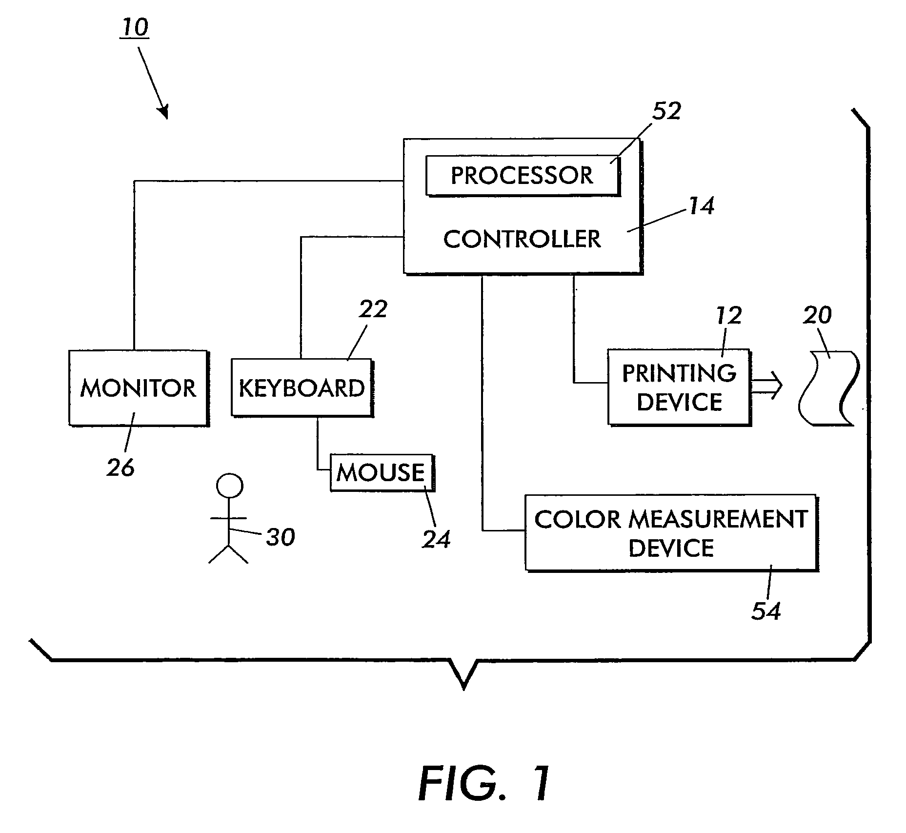
[0025]With reference to FIG. 1, a system 10 for compensating for a calibration drift includes an electronic printer output device (“printing device”) 12, also referred to as an image output terminal (“IOT”), and a printer output device controller (“controller”) 14 (image data generator). In the preferred embodiment, the printing device is a color printer. However, it is also contemplated that the printing device be a black-and-white printer or a color and black-and-white facsimile machine.

[0026]The controller 14 converts original image data (e.g., PostScript® or PDF format), which is received by the controller 14, to final image data (e.g., raster data). The final image data is transmitted from the controller 14 to the printing device 12, which renders the image data on an output medium 20. In the preferred embodiment, the output medium is some type of paper (e.g., glossy or semi-glossy). However, other types of output media (e.g., plastic transparency) are also contemplated.

[0027]B...


PUM


Abstract

A system for compensating for a calibration drift in an image output device includes a user input means for specifying an output medium. An image output device controller converts original image data to final image data used by the image output device. The image output device produces a calibration image, as a function of an output medium, for a plurality of halftone screens capable of being produced by the image output device. A processor communicates with the controller. The processor calculates a plurality of candidate tone reproduction curve sets for the specified output medium. Each of the sets corresponds to one of the plurality of halftone screens. The candidate tone reproduction curve sets are accepted for compensating for a calibration drift in the image output device.

Description

BACKGROUND OF THE INVENTION[0001]The present invention relates to calibrating an electronic printer output device. It finds particular application in conjunction with calibrating an electronic printer output device using a tone reproduction curve (“TRC”) and will be described with particular reference thereto. It will be appreciated, however, that the invention is also amenable to other like applications.[0002]An electronic printer output device (“printing device”), also referred to as an image output terminal (“IOT”), is generally capable of producing color and standard black-and-white tones to produce images. The printing device accepts color level specifications (typically for each of four (4) colors including cyan, magenta, yellow, and black (“CMYK”)) as input and produces corresponding color areas on a printed page. This production of the corresponding color areas is often performed by a screening operation (also referred to as a halftoning operation) wherein a fine pattern of ...

Claims


Application Information

Patent Timeline
Patent Type & Authority Patents(United States)
IPC IPC(8): H04N1/60H04N1/407H04N1/40B41J29/38B41J5/30B41J21/00H04N1/23H04N1/46
CPCH04N1/40006H04N1/4078H04N1/6027H04N1/6033H04N1/6097
Inventor HENDERSON, TODD R.DEGANI, AMMAR T.WIEGAND, MICHAEL A.EDDY, RICHARD J.
Owner XEROX CORP
Why Eureka
Try Eureka