Apparatus and method for commissioning and diagnosing control systems

Active Publication Date: 2005-11-15
SIEMENS AG
View PDF14 Cites 10 Cited by
  • Summary
  • Abstract
  • Description
  • Claims
  • Application Information

AI Technical Summary

Benefits of technology

[0005]The object of the present invention is to provide the user with the most intuitive and simplest way of observing and optimizing the state of the control system and the behavior of the machine sequence. This object is achieved by an apparatus for commissioning and/or diagnosing control systems, having a d

Problems solved by technology

The increasing complexity of automatic machines likewise requires mor

Method used


Image

  • Apparatus and method for commissioning and diagnosing control systems
  • Apparatus and method for commissioning and diagnosing control systems
  • Apparatus and method for commissioning and diagnosing control systems

Examples


Embodiment Construction

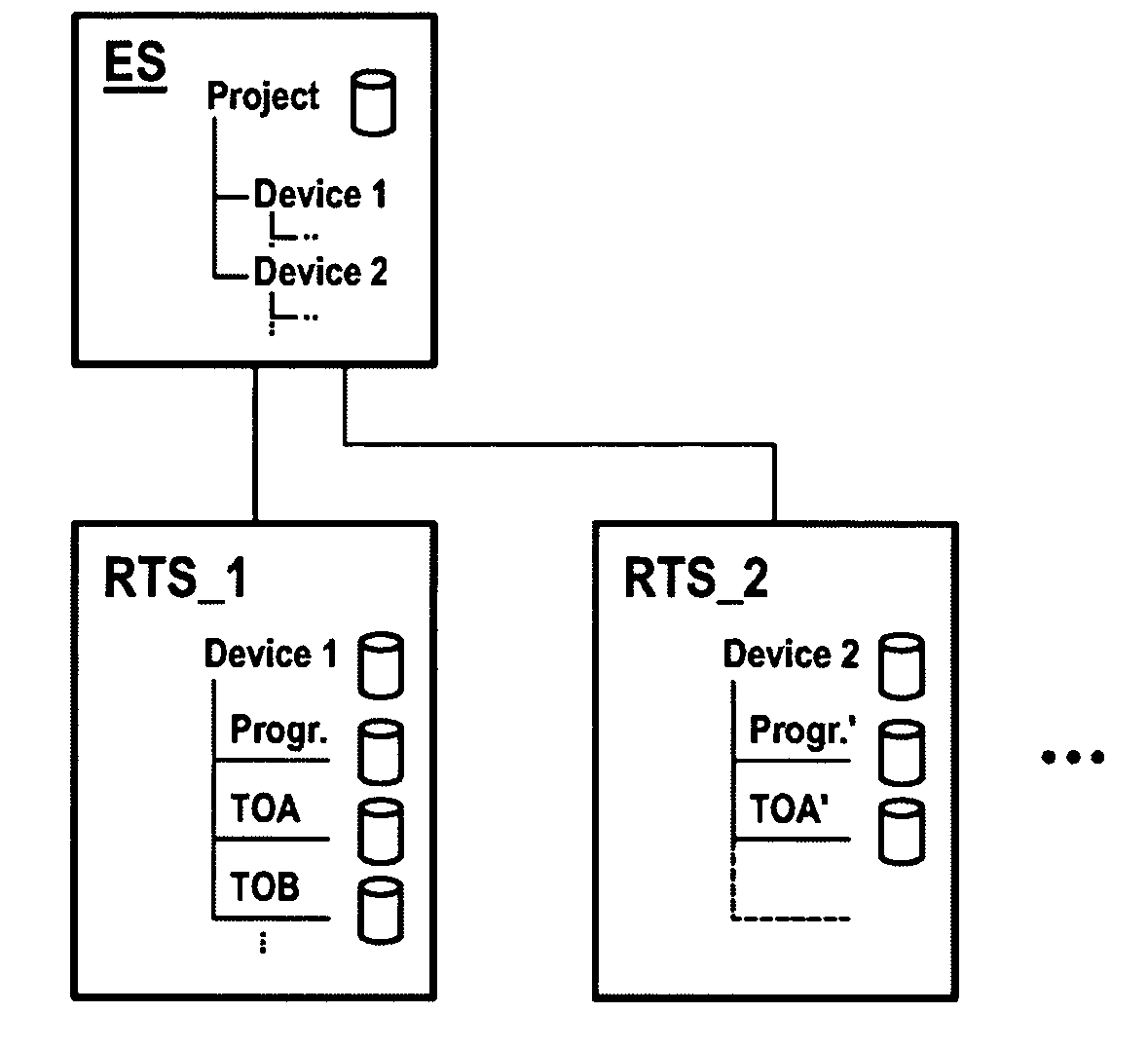
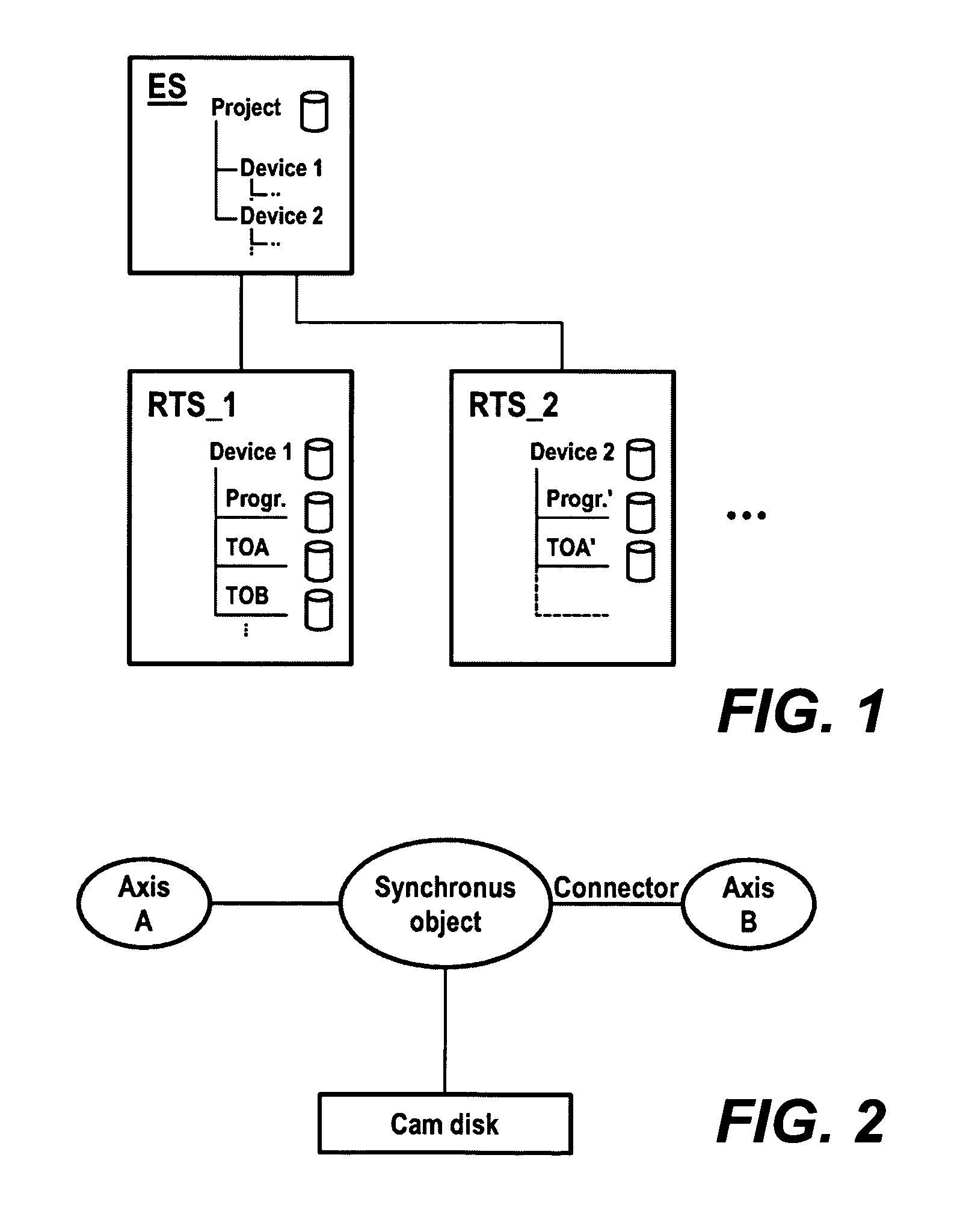
[0013]FIG. 1 illustrates a control system for automation in schematic form. The control system comprises an engineering system ES with which a control program can be compiled. Furthermore, the control system comprises one or more run-time systems RTS. In the engineering system ES, a control program is developed which is based on an object model. The object model comprises technological objects, such as positioner axes, synchronous axes, cam disks, etc., each of which can be connected to other technological objects or to one another in accordance with their functionality. By using one or more connected technological objects TOA, TOB, etc., together with an appropriate program, the control of a device (Device 1, Device 2, etc.) may be formulated.

[0014]FIG. 1 shows that with the aid of the engineering system ES different device controllers Device 1, Device 2, can be implemented for a plurality of run-time systems RTS—1, RTS—2 within a project. It is therefore possible for different con...


PUM


Abstract

The engineering of automation systems is configured more simply where the functionality of a control system is implemented via an object model. The object model permits the functional interconnection of technological objects. For this purpose, a project browser ensures the display of the interplay of all the components involved in an application in their mutual relationships.

Description

CROSS REFERENCE TO RELATED APPLICATION[0001]This application claims foreign priority to German application number 10064798.7 filed Dec. 22, 2000 and German application number 10125384.2 filed May 23, 2001.FIELD OF THE INVENTION[0002]The present invention relates to an apparatus and method for commissioning and diagnosing control systems. In particular, the present invention relates to an apparatus having an engineering system for compiling a control program.BACKGROUND OF THE INVENTION[0003]The commissioning, operation and diagnosis of automation systems and drives are increasingly carried out completely electronically. Mechanical systems and drives of automatic machines are controlled by microcontrollers, using appropriate software (run-time systems). The corresponding control programs are developed on a PC in an engineering system, and subsequently loaded into the run-time system which is responsible for the timed control of the system to be controlled. The engineering system is al...

Claims


Application Information

Patent Timeline
IPC IPC(8): G05B19/042G05B19/04
CPCG05B19/0426G05B2219/25428Y10S715/97Y10S715/967Y10S715/965
Inventor BUNGERT, ULRICHKIESEL, MARTIN
Owner SIEMENS AG
Why Eureka
Try Eureka