Method of designing geophysical surveys

a geophysical survey and design technology, applied in seismology for waterlogging, instruments, analogue processes for specific applications, etc., can solve the problems of limiting the ability to place sources, not being able to have a completely free hand, and complex design of the survey

Inactive Publication Date: 2005-11-15
SCHLUMBERGER TECH CORP
View PDF12 Cites 16 Cited by
  • Summary
  • Abstract
  • Description
  • Claims
  • Application Information

AI Technical Summary

Benefits of technology

[0013]designating one or more potential source positions acc

Problems solved by technology

Also, P-S conversion in the waves can result in asymmetry.
Therefore, the problem of designing them is more complex.
However, it is often the case that it is not possible to have a completely free hand when it comes to positioning the source and receivers.
For example, surface geographical features (rivers, lakes, cliffs, gullies, etc.) can limit the ability

Method used


Image

  • Method of designing geophysical surveys
  • Method of designing geophysical surveys
  • Method of designing geophysical surveys

Examples


Embodiment Construction

[0025]The present invention will now be described by way of example, with reference to the accompanying drawings. In the particular case described, the invention is implemented in a software environment such as GeoFrame available from Schlumberger GeoQuest but it will be appreciated that the methodology described can be applied to other such environments while still retaining the essential features of the invention and so is not limited to implementation in this environment. Unless otherwise specified, functional elements referenced in this description can be found in GeoFrame.

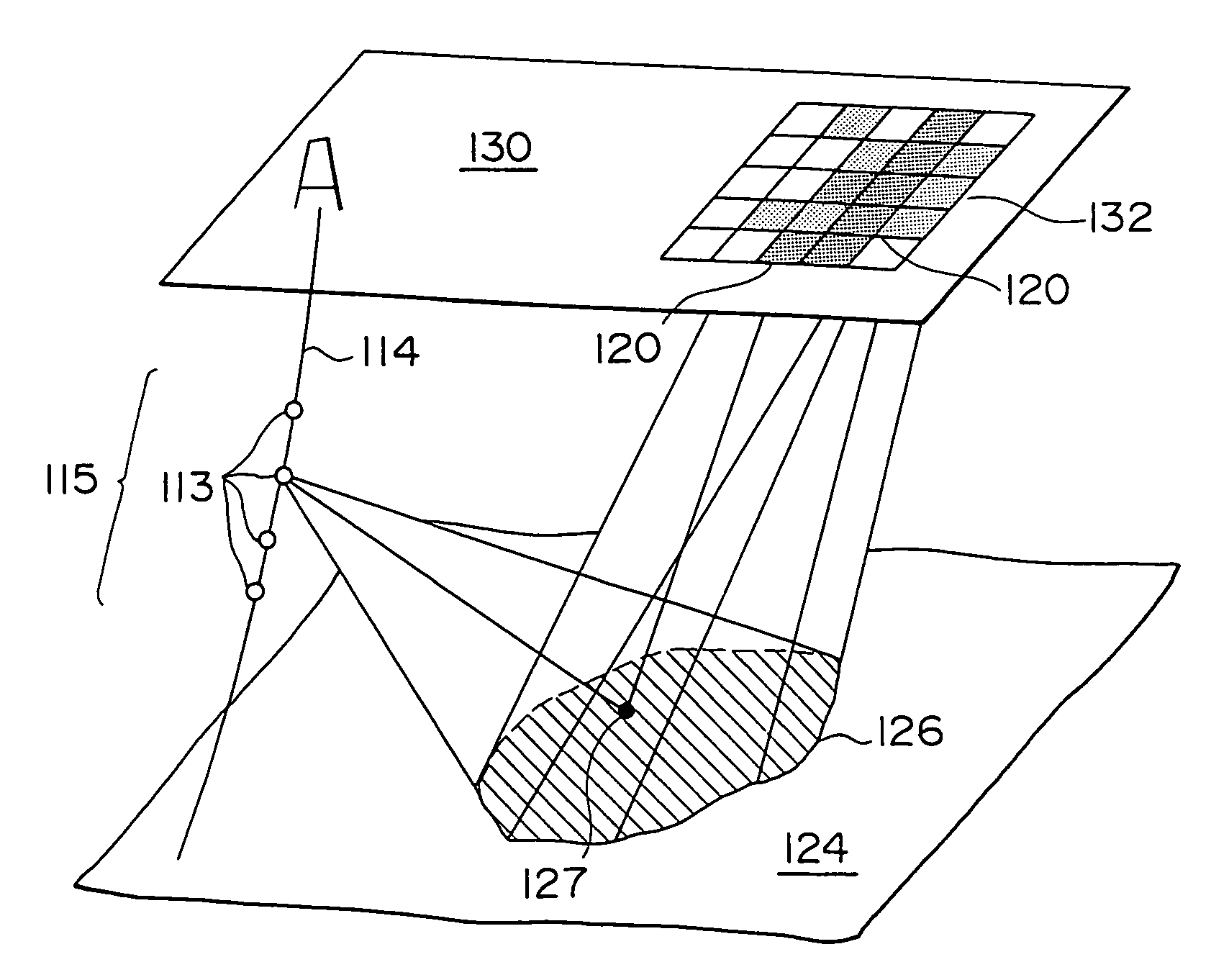
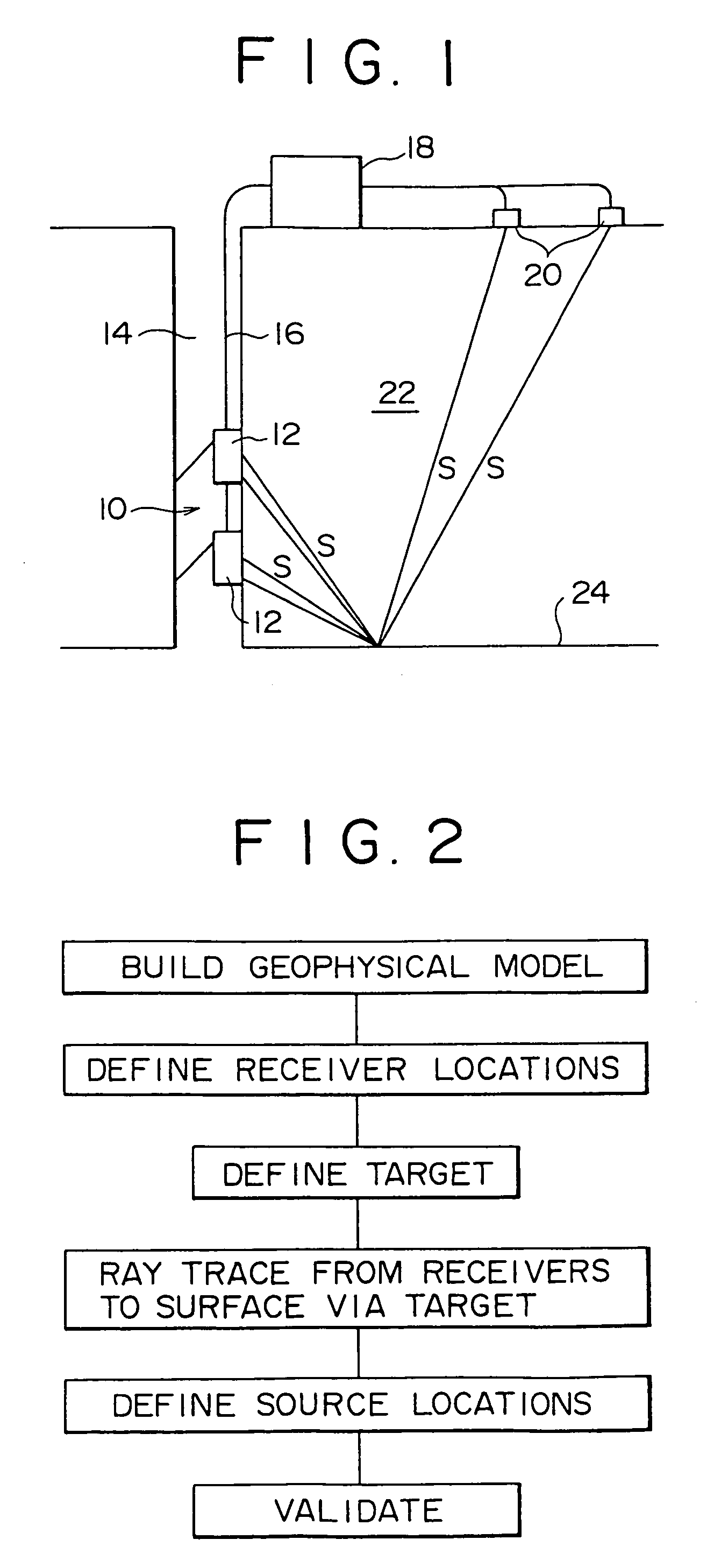
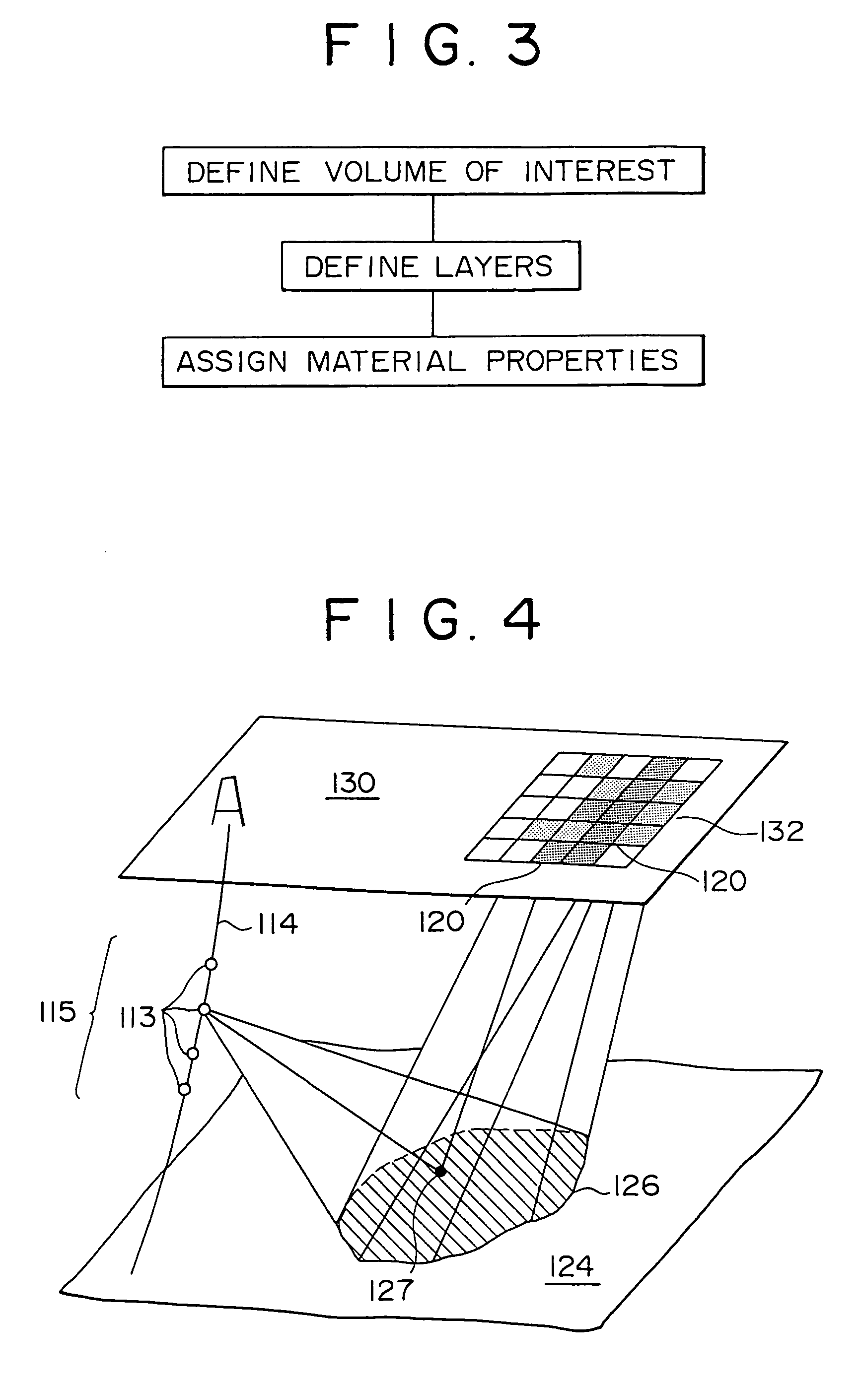
[0026]The embodiment of the invention described here is the design of a VSP survey for the purpose of imaging a reef in the formations surrounding the well in question. The basic steps are shown in FIG. 2 and in this case comprise:[0027]building a geophysical model;[0028]defining receiver locations in the well within the model;[0029]defining the target (e.g. reef);[0030]ray tracing from receivers to surface vi...


PUM


Abstract

A method for the design of VSP surveys for the purpose of imaging a reef in the formations surrounding the well in question. The basic steps include:
    • building a geophysical model;
    • defining receiver locations in the well within the model;
    • defining the target (reef);
    • ray tracing from receivers to surface via target;
    • defining source locations on surface based on ray density pattern; and
    • validate by ray tracing from source locations to receiver locations via target.

Description

FIELD OF THE INVENTION[0001]The present invention relates to methods for designing geophysical surveys such as seismic surveys. In particular, the methods involve determining the positions of sources and receivers for conducting the survey, especially in borehole seismic surveys such as vertical seismic profiles.BACKGROUND OF THE INVENTION[0002]The general arrangement of a vertical seismic profile (VSP) survey is shown in FIG. 1. A tool 10, typically comprising and array of seismic receivers (e.g. geophones) 12, is positioned in a borehole 14 by means of a logging cable 16 connected to surface equipment 18. One or more seismic sources 20 (e.g. airguns) are positioned at the surface some distance from the borehole 14. When the source(s) is fired, seismic waves S travel through the formations 22 surrounding the borehole 14 and are reflected in part from changes in acoustic impedance in the formations due to the presence of bed boundaries 24, and are detected by the receivers 12 in the...

Claims


Application Information

Patent Timeline
IPC IPC(8): G01V1/40G01V1/42
CPCG01V1/42G01V2210/161
Inventor CAO, DIHARA, KENZO
Owner SCHLUMBERGER TECH CORP
Why Eureka
Try Eureka