
Valve core for single handled faucet

a valve core and faucet technology, applied in the direction of valve details, valve arrangement, thin material handling, etc., can solve the problem of protruding guides, etc., and achieve the effect of less force, stable refraining, and easy operation of the valve stick

Inactive Publication Date: 2005-11-22
KUCHING INT
View PDF9 Cites 16 Cited by
  • Summary
  • Abstract
  • Description
  • Claims
  • Application Information

AI Technical Summary

Benefits of technology

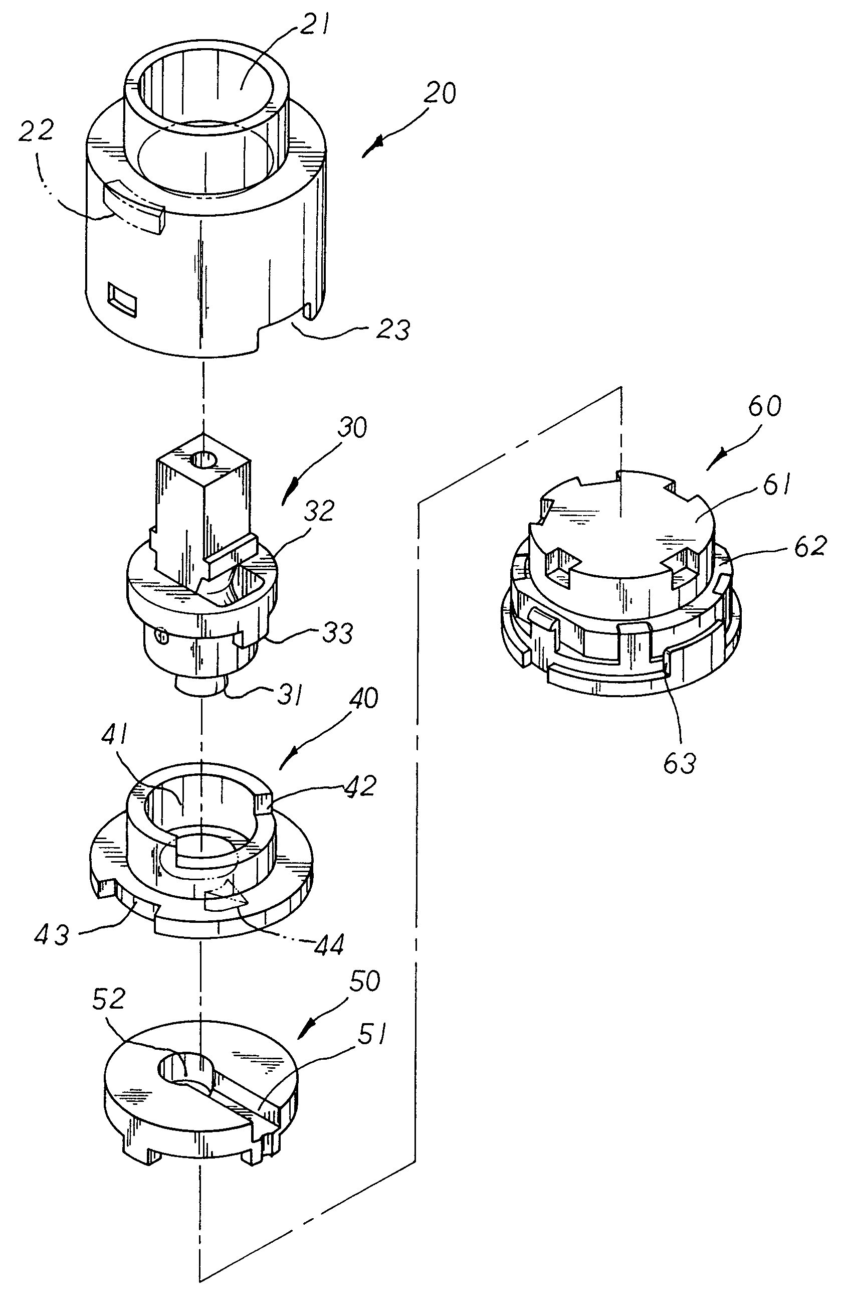
"The present invention provides a valve core for a single handled faucet with a secure and stable valve housing. The valve stick is pivotally moved at the base mount and activates the switching control valve to open the valve core for water discharge. The valve stick can also be rotated to adjust the water temperature. The valve stick and two-staged valve stick seat are prevented from being directly contacted with the valve housing, facilitating easy operation with less force. The protruded guide spot of the base mount is limited to move at an indented recess of the switching control valve therein, ensuring the precise movement of the switching control valve thereof when activated by the valve stick to open the valve core for water discharge. The valve housing is provided with a retaining block disposed at the inner top surface thereof to be engaged with a retaining cavity of the base mount for secure location thereof, greatly simplified in structure and reduced in the costs of materials and production thereof."

Problems solved by technology

Besides, a protruded guide spot of the base mount is limited to move at an indented recess of the switching control valve therein, ensuring the precise movement of the switching control valve in operation.
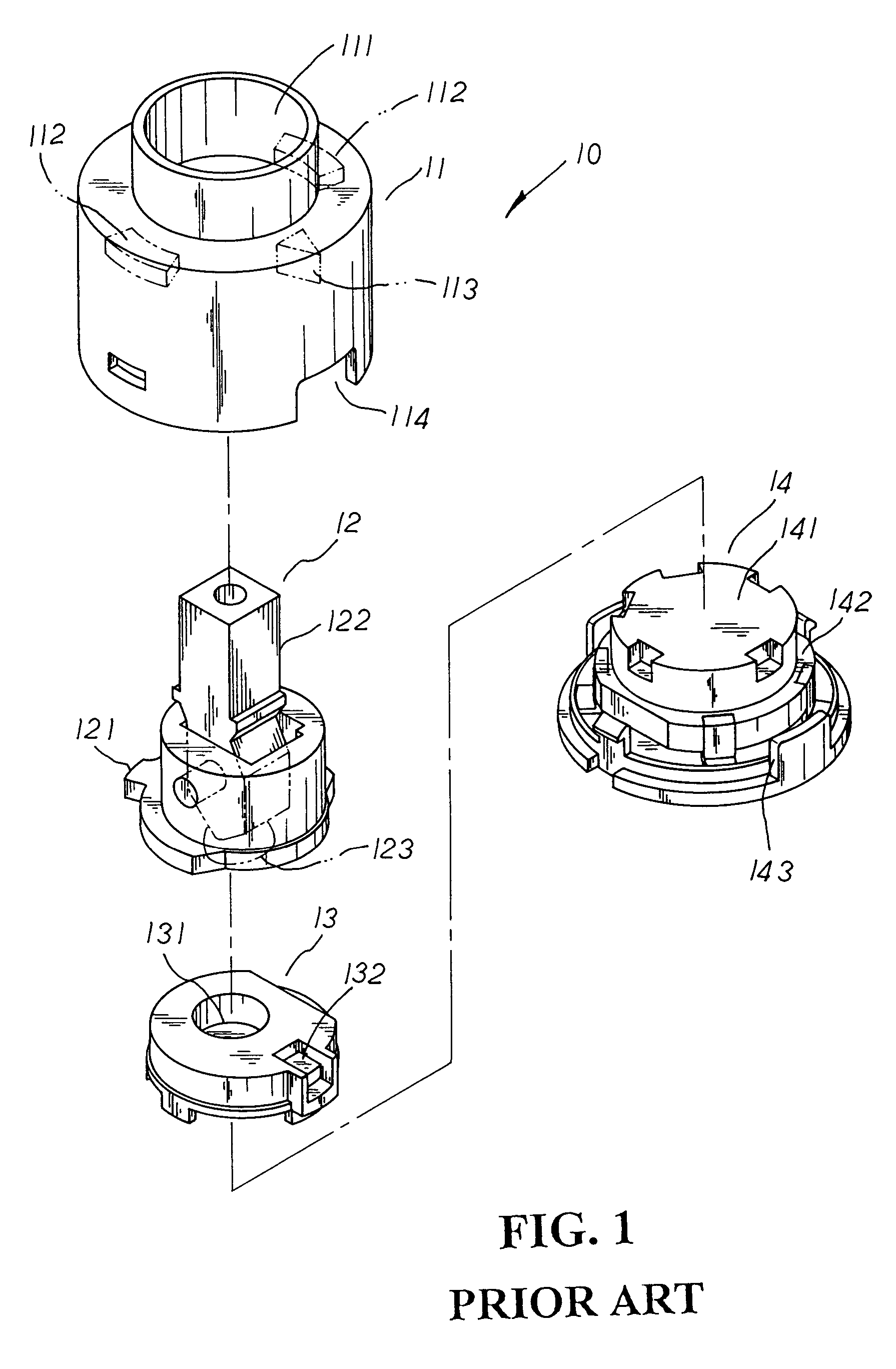
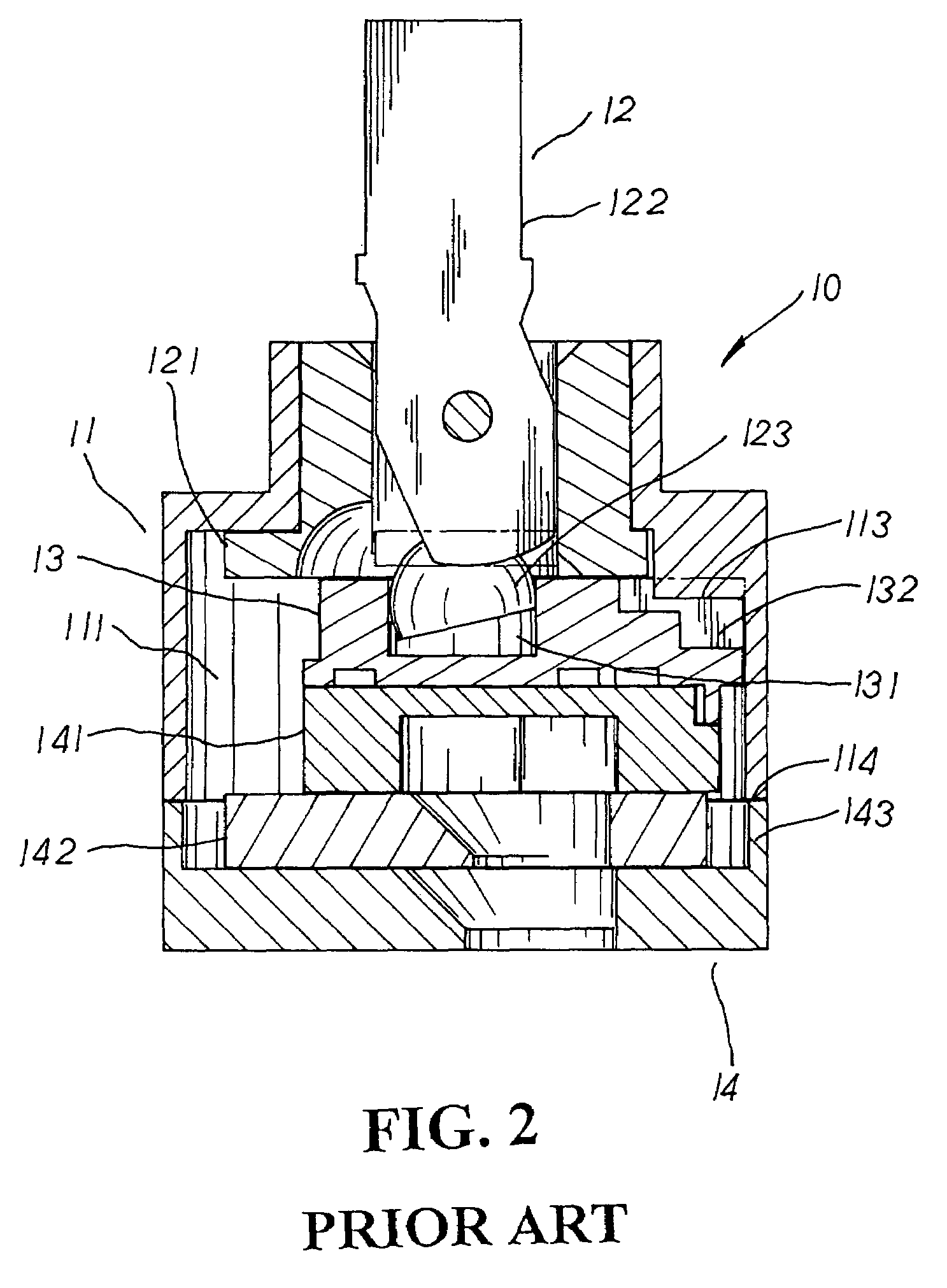
There are some drawbacks to such conventional valve core 10 for a single handled faucet.

Method used


Image

  • Valve core for single handled faucet
  • Valve core for single handled faucet
  • Valve core for single handled faucet

Examples


Embodiment Construction

[0013]Please refer to FIG. 3. The present invention is related to a valve core for a single handled faucet, comprising a valve housing 20, a valve stick 30, a base mount 40, a switching control valve 50, and a valve seat 60. The valve housing 20, a two-staged sheltering case, has a valve chamber 21 disposed at the interior thereof, a retaining block 22 protruding at the inner top surface of the valve chamber 21 thereof, and a plurality of insert grooves 23 cut at the lower periphery thereof. The valve stick 30 is provided with a protruded connecting section 31 extending downwards at the bottom thereof, and a two-staged valve stick seat 32 with a turning protruded block 33 extending downwards at one side of the upper stage thereof joined at the middle section thereof. The base mount 40, a two-staged means, is equipped with a pivot hole 41 disposed at the center thereof, a turning cut area 42 defined at one side of the upper section thereof, a retaining cavity 43 cut at one side of th...


PUM


Abstract

A valve core for a single handled faucet is made up of a valve housing, a valve stick, a base mount, a switching control valve, and a valve seat wherein the base mount, engaged with the valve stick and mounted onto the switching control valve thereof, is securely located at the valve housing therein, stably refrained from being moved or rotated by the valve stick thereof in operation. The valve stick is pivotally moved at the base mount therein to activate the switching control valve via a protruding connecting section thereof, driving an upper switch valve of the valve seat joined to the bottom of the switching control valve thereof to open the valve core for water discharge. Via a protruded guide spot of the base mount as a pivoting point, the valve stick is also rotated left or right with a turning protruded block thereof moved at a turning cut area of the base mount therein to adjust the water temperature. Meanwhile, the valve stick along with a two-staged valve stick seat is prevented from being directly contacted with the valve housing in operation, facilitating the easy operation of the valve stick thereof even under low torque. Besides, the protruded guide spot is limited to move at an indented recess of the switching control valve therein, ensuring the precise movement of the switching control valve when activated by the protruded connecting section of the valve stick to open the valve core for water discharge.

Description

BACKGROUND OF THE INVENTION[0001]The present invention is related to a valve core for a single handled faucet, comprising a valve housing, a valve stick, a base mount, a switching control valve, and a valve seat wherein the base mount, engaged with the valve stick and mounted onto the switching control valve thereof, is securely located at the valve housing therein, stably refrained from being moved or rotated by the valve stick thereof in operation. The valve stick, pivotally moved at the base mount therein, will activate the switching control valve via a protruded connecting section, driving an upper switch valve of the valve seat joined at the bottom thereof for water discharge. The valve stick is also rotated left or right with a turning protruded block thereof moved at a turning cut area of the base mount therein to adjust the water temperature. Meanwhile, the valve stick thereof is prevented from being directly contacted with the valve housing, facilitating the easy operation ...

Claims


Application Information

Patent Timeline
Patent Type & Authority Patents(United States)
IPC IPC(8): F16K31/60F16K11/06F16K11/078
CPCF16K11/0782F16K31/605Y10T137/86549Y10T137/86815Y10T137/8708
Inventor CHEN, MEI-LI
Owner KUCHING INT
Learn More