
Conveyor system for article treatment

a conveyor system and article technology, applied in the direction of rope railways, furniture, charge manipulation, etc., can solve the problems of chain wear, pendulums tend to become misaligned, and need for two separate return paths, and achieve the effect of cost and efficiency

Inactive Publication Date: 2005-11-22
JERVIS B WEBB INT CO
View PDF68 Cites 17 Cited by
  • Summary
  • Abstract
  • Description
  • Claims
  • Application Information

AI Technical Summary

Benefits of technology

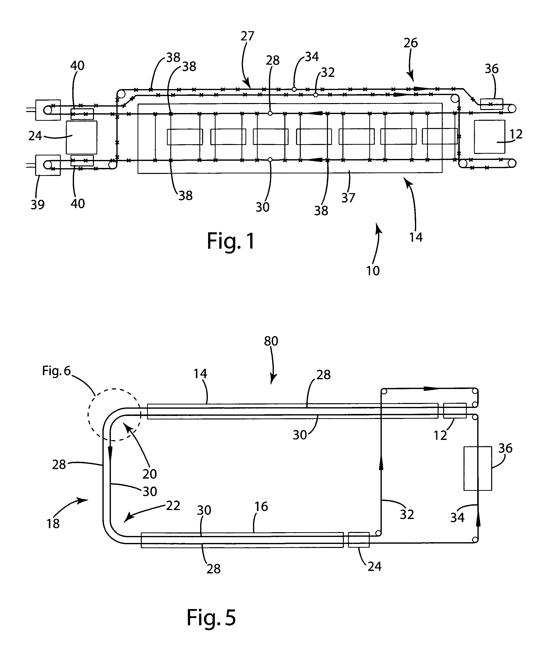
[0008]The present invention is directed to an installation for conveying articles through a dipping tank and to a conveyor and method for conveying such articles. The invention includes numerous embodiments including an installation and conveyor using a single chain to transport pendulums in spaced apart and aligned pairs through treatment areas. The single chain conveyor embodiment provides numerous cost and efficiency benefits when compared to the prior art.
[0010]A still further feature of the present invention is an embodiment that permits the articles to be transported around horizontal curves using the same pendulums that support the article through linear segments of the treatment area.

Problems solved by technology

Each of these different components give rise, both individually and in combination, to different stresses and generate differing forces that tend to deteriorate the separate chains over time.
These forces in turn cause chain wear, such as a narrowing of the diameter of chain pins that intercouple adjacent links as well as a broadening of the pin passages in the chain links.
As the length of each chain changes, the pendulums tend to become misaligned.
A further disadvantage of the two conveyor system described above is the need for two separate return paths between the point that the vehicle bodies are unloaded and loaded.
Yet still another disadvantage of the prior art system described above is the inability of the separate conveyors to transport the vehicle body around horizontal turns.
Due to space constraints and the length of the required dipping lines, it is common to have two or more parallel treatment paths through which each vehicle must pass.
The unloading from the first line, rotation, horizontal displacement, further rotation, and loading onto the second line requires a complex and expensive array of lifts, turntables, and roller tables.
All of these components are required simply because existing pendulum conveyor systems cannot transport the vehicle bodies around horizontal curves.
The inability of prior art systems to traverse horizontal curves results in part from the chording of the spaced pendulums on each conveyor and the need to maintain alignment of the pendulum pairs.
This spacing creates a chordal distance between adjacent pendulums on each of the spaced and separate chains that cannot be effectively accommodated in a horizontal turn.

Method used


Image

  • Conveyor system for article treatment
  • Conveyor system for article treatment
  • Conveyor system for article treatment

Examples


Embodiment Construction

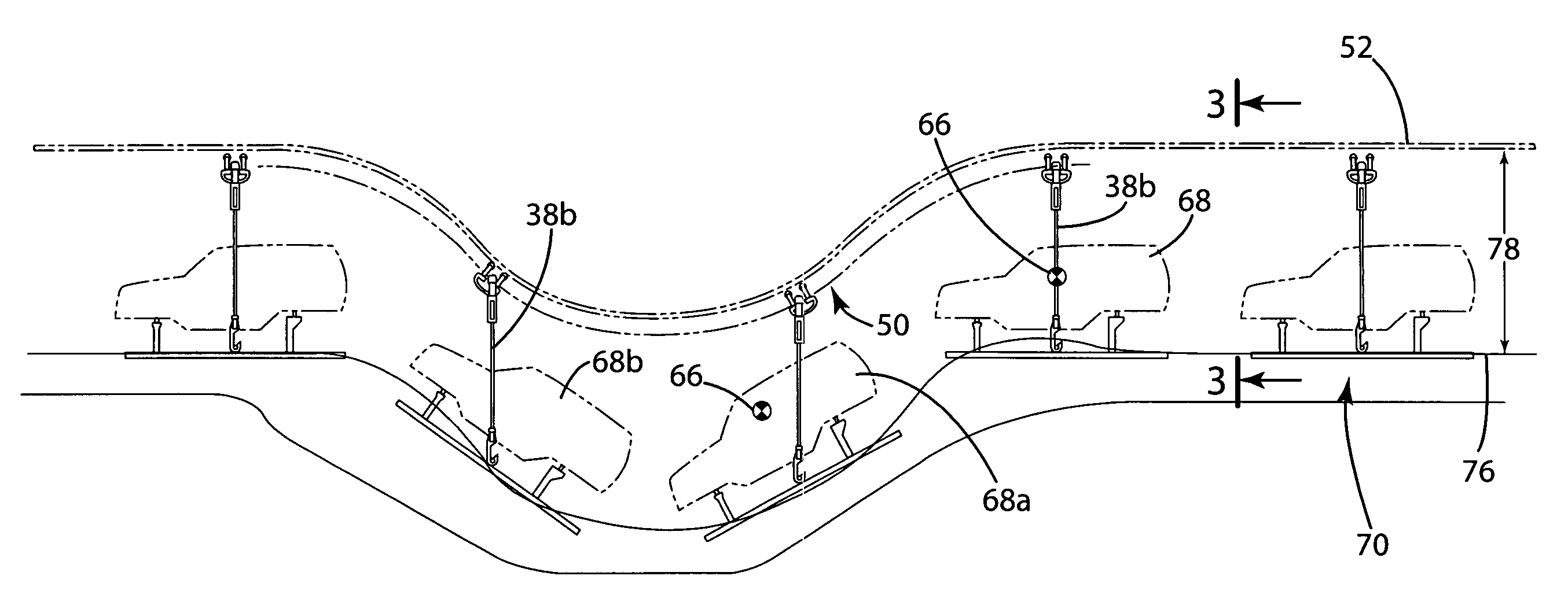
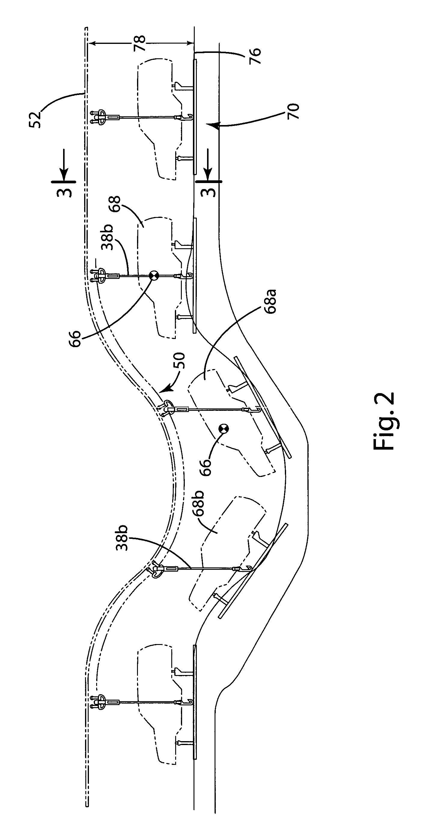
[0029]The present invention will now be described in detail with reference to attached FIGS. 1–16. While the following description relates in part to a single chain conveyor system, those skilled in the art will appreciate from this description that several of the embodiments of the invention, as well as the advantages attendant thereto, may be used in systems using two separate conveyors. Moreover, various modifications may be made to the described embodiments without departing from the proper scope of the invention.

[0030]FIG. 1 illustrates a treatment installation 10 having a load station 12 wherein articles such as vehicle bodies may be loaded onto the conveyor system for transport through a first treatment area 14. The vehicle bodies may be subjected to numerous treatment operations. For example, as will be further described, the vehicle bodies may be dipped in solutions for the preparation of the body for painting. An unload station 24 is provided at the downstream end of the t...


PUM


Abstract

A system for transporting articles along a treatment path in a treatment area. The conveyor system includes a conveyor and a plurality of pendulums. The conveyor includes first and second drive segments laterally spaced from and parallel to one another. The pendulums include first pendulums moving along the first drive segment and second pendulums moving along the second drive segments in aligned and opposed pairs. Further features of the invention include a guide assembly having a first element coupled to move with a carrier assembly and a second element engaging the first element to stabilize the rotational orientation of the carrier assembly. Other features of the present invention include a conveyor system configuration that facilitates transportation of articles about horizontal curves as well as a unique pendulum configuration particularly suited for use with the invention.

Description

CROSS-REFERENCE TO RELATED APPLICATION[0001]This application claims the benefit of U.S. Provisional Application No. 60 / 359,684, filed Feb. 26, 2002, the entire disclosure of the application is considered part of the disclosure of this application and is hereby incorporated by reference.BACKGROUND OF THE INVENTION[0002]The present invention relates generally to a conveyor, installation, and method for moving articles and, more particularly, for moving articles, such as vehicle bodies, through a series of dip tanks.[0003]Various conveyor systems are available to transport articles such as vehicle bodies through production areas. Of particular interest for the present invention are conveyor systems that move articles, such as vehicle bodies, through a series of dip tanks for treating the vehicle body prior to painting. Conveyor systems of this type are generally required to transport the vehicle body along the path of travel in a manner that supports the vehicle body in a variety of or...

Claims


Application Information

Patent Timeline
Patent Type & Authority Patents(United States)
IPC IPC(8): B61B10/02B61B10/00B65G49/00B65G49/04
CPCB61B10/02B65G49/0463B65G2201/0294
Inventor JAYNES, JOHN H.STEWART, DAVID M.AUDIA, CHRISTOPHER L.SCHELL, KELSEY R.KUBSIK, ROBERT H.EDWARDS, MELVIN
Owner JERVIS B WEBB INT CO
Learn More