
Rotatable retracting apparatus

Active Publication Date: 2005-11-22
HAMMERHEAD INDS
View PDF4 Cites 86 Cited by
  • Summary
  • Abstract
  • Description
  • Claims
  • Application Information

AI Technical Summary

Benefits of technology

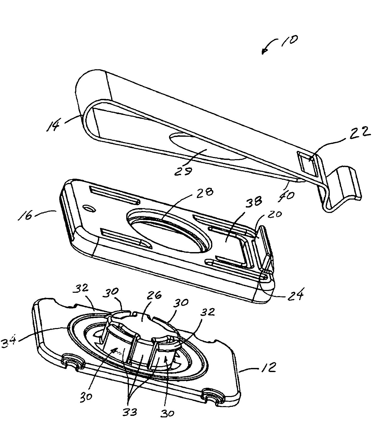
[0011]The present invention seeks to provide a tethering device that is rugged, easy to manufacture and assemble, and provides smooth rotation between the retractor housing and the attachment mechanism. One embodiment of a rotation device according to the present invention that can be used with a retractor, comprises a base having a locking post, the base being mounted to a first body. An attachment mechanism is included for attaching to a second body and a retaining section is also included, the attachment mechanism integral to the retaining section. The retaining section has a retaining section hole sized to mate with the locking post and the locking post has a mechanism for holding the post in the retaining section hole. The inside surface of the retaining section hole rides on the outside surface of the locking post to provide for smooth rotation of the retaining section in relation to the base.
[0012]An embodiment of a retracting tether apparatus according to the present invention comprises a retractor housing having a locking post on its outside surface. It also includes an attachment mechanism for attaching to a body and a retaining section, the attachment mechanism being integral to the retaining section. The retaining section has a retaining section hole sized to mate with the locking post and the locking post has a mechanism for holding the post in the retaining section hole. The inside surface of the retaining section hole rides on an outside surface of the locking post to provide for smooth rotation of the retractor housing in relation to the retaining section.
[0013]The attachment mechanism in each of the embodiments can comprise a belt clip that can be securely attached to a belt, pants, pocket, strap or purse. The retractor can rotate freely about the attachment mechanism through a full 360-degree rotational motion. This reduces the wear on the cable when the device attached to the cable not in use, and also when the cable is extracted during use of the device.

Problems solved by technology

One disadvantage of most conventional retractable tethering devices (“tethering devices”) using a belt clipping system is that when the retracting tether is mounted, it is generally in a fixed orientation in relation to its mounting point.
This causes excessive resistance and cable flexing or fatigue which can result in reduced overall life of the product.
This arrangement will likely result in a resistance between the belt clip, mounting bolt and housing and if the components are made of metal, this arrangement results in metal to metal wear.
Further, any side torque on the housing could result in a torque on the belt clip causing the mating surfaces to bend, which can destroy the device's rotational capability.
Further, rotational axis of the device is provided internal to the housing, which can cause complication in the design and operation of the housings internal spring arrangement.
Although it is unclear how this arrangement actually works, it appears to suffer from the same disadvantages as Huang.
The bushing sleeve spans the interior of the housing such that is can interfere with the operation of the internal spring.
Poulson does not disclose how the rotation riding surfaces are arranged but it likely has metal on metal moving parts that would also likely suffer from the resistance of adjacent moving metal surfaces and the resulting wear.

Method used


Image

  • Rotatable retracting apparatus
  • Rotatable retracting apparatus
  • Rotatable retracting apparatus

Examples


Embodiment Construction

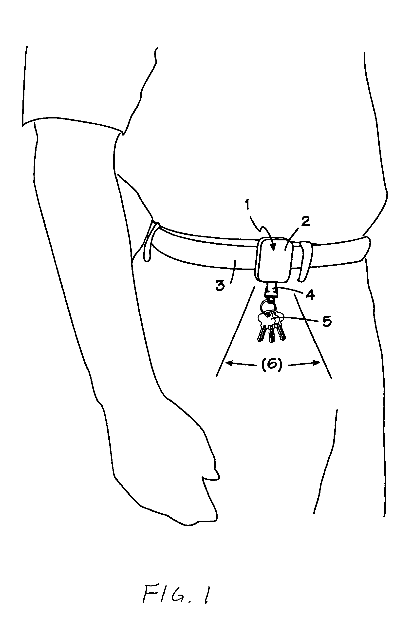
[0023]FIG. 1 shows one embodiment of a tethering device 1 according to the present invention, which generally comprises a retractor 2 and rotating attachment mechanism that is further described below and shown in FIGS. 3 and 4. The attachment mechanism can attach to the user's belt, pants, pocket, strap or purse, with the mechanism shown attached to the user's belt 3. The apparatus 1 can utilize many different attachment mechanisms and many different retractors.

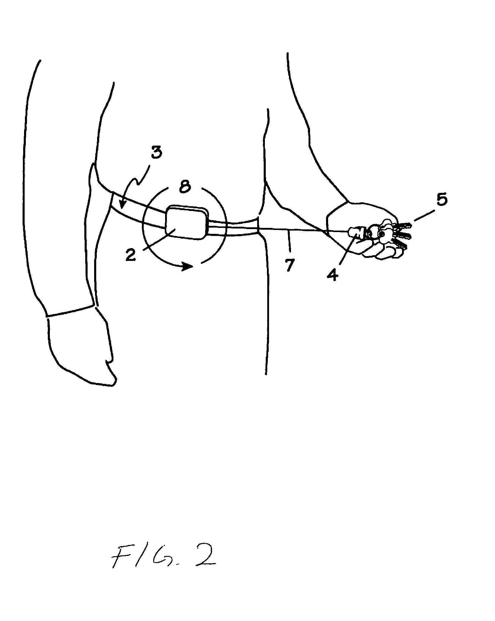
[0024]According to the present invention, the retractor 2 is capable of rotating 360 degrees about its mounting point, in a plane parallel to the attachment mechanism's plane. The retractor 2 has an internal cable (shown in FIG. 2) that can be extended against the force of an internal spring. When the extending force is removed, the cable is retracted into the retractor under the spring force. The mechanism for extending and retracting the cable from the retractor 2 is known in the art and can involve a coil spring and reel a...


PUM


Abstract

A retracting tether apparatus is disclosed comprising a retractor housing having a locking post on its outside surface. The apparatus also includes an attachment mechanism, such as a belt clip, for attaching to a body and a retaining section, the attachment mechanism being integral to the retaining section. The retaining section has a retaining section hole sized to mate with the locking post and the locking post has a mechanism for holding the post in the retaining section hole. The inside surface of the retaining section hole rides on an outside surface of the locking post to provide for smooth rotation of the retractor housing in relation to the retaining section.

Description

[0001]This application claims the benefit of provisional application No. 60 / 388,462 to Salentine et al., which was filed on Jun. 13, 2002.BACKGROUND OF THE INVENTION[0002]1. Field of the Invention[0003]Present invention relates to retracting tethers and more particularly to a retracting tether apparatus mounted to a user's belt, pants, pocket, strap or purse, and arranged to be 360 degrees rotatable about its mounting point.[0004]2. Description of the Related Art[0005]Retractable tethering devices have been developed that can be attached to a person through use of common attachment mechanisms such as snaps, clips, Velcro straps, pin mounting systems, bracket mounting devices and belt clipping devices. Conventional belt clipping and bracketing systems are desirable for some applications in that they are easy to mount to an article of clothing that does not have means for attaching a snap, Velcro or pinning attachment. A belt clipping system also provides an attachment means that redu...

Claims


Application Information

Patent Timeline
IPC IPC(8): A45F5/02A45F5/00
CPCA45F5/004A45F5/02A45F5/021A45F2200/0516A45F2200/0558Y10S224/93
Inventor SALENTINE, JOHN A.COLLIN, JR., KENNETH S.
Owner HAMMERHEAD INDS
Learn More