Airship and method of operation

a technology of airships and airframes, applied in the field of balloon aircraft and operation, can solve the problems of not having the endurance required, the development and launch cost of spacecraft may tend to be very high, and the use of free balloons or tethered balloons is not suitable, so as to achieve the effect of long enduran

Inactive Publication Date: 2005-11-22
21ST CENTURY AIRSHIP TECH
View PDF45 Cites 53 Cited by
  • Summary
  • Abstract
  • Description
  • Claims
  • Application Information

AI Technical Summary

Benefits of technology

[0018]The present inventor employs a spherical airship as a platform for relatively high altitude observation, or communications, with a tendency to permit relatively long endurance loitering in a particular location. The present inventor has also noted, that for either high or low altitude flight, it is advantageous to shift the point of separation of the flow to a relatively rearward location.

Problems solved by technology

While a geostationary satellite system may have a large “footprint” for communications or surveillance purposes, this may be higher than is desirable for high resolution observation, and the development and launch cost of a spacecraft may tend to be very high.
Free balloons or tethered balloons would not tend to be suitable: a free balloon is not tethered, and will tend not to stay in one place; a 40,000–60,000 ft tether is not practicable (a) because of the weight of the tethers themselves; and (b) because of the danger to aerial navigation.
Heavier-than-air aircraft tend not to have the required endurance, and any aircraft that relies on airflow over a lifting or other control surface must maintain sufficient velocity to maintain control, a problem that worsens when the density of the atmosphere is reduced.
Modern airships that rely on the buoyancy of a lifting gas may tend to suffer from a number of disadvantages, such as (a) poor low-speed manoeuvrability; (b) the need for relatively large ground-crews for take-offs and landings; (c) the need for relatively large fields from which to operate; (d) complicated and expensive infrastructure for mooring (parking); and (e) susceptibility to damage in turbulent atmospheric conditions.
In the view of the present inventor, many, if not all of these disadvantages appear to stem from the fundamental shape and configuration of traditional airships—that is, the characteristic elongated, finned hull.
Below 10 to 15 km / h (6–10 mph), there tends no longer to be sufficient airflow over the fins' control surfaces, making them ineffectual.
When the inner envelope is fully expanded, the airship is at pressure altitude; meaning that it cannot climb higher without valving some lifting gas.
Traditional cigar shaped blimps may also tend to present other disadvantages when viewed in the context of an aircraft having a high altitude service ceiling.
This may present significant control challenges at low altitude for a cigar shaped aircraft.
Further, conventional airships tend to rely on airflow over their control surfaces to manoeuvre in flight.
Further still, blimps and dirigibles are known to be susceptible to “porpoising”.
In a light or “no-wind” situation, it may be difficult to maintain a cigar shaped dirigible “on station”, i.e., in a set location for which the variation in position is limited to a fixed range of deviation such as a target box 1 km square relative to a ground station.
Deflecting the propwash downward may tend to cause the airship to ascend; deflecting the propwash upward may tend to cause the airship to descend.
Landing procedures are comparatively uncomplicated.
This may tend to result in a relatively low leakage rate of the lifting gas.

Method used


Image

  • Airship and method of operation
  • Airship and method of operation
  • Airship and method of operation

Examples


Embodiment Construction

[0044]The description that follows, and the embodiments described therein, are provided by way of illustration of an example, or examples, of particular embodiments of the principles of the present invention. These examples are provided for the purposes of explanation, and not of limitation, of those principles and of the invention. In the description, like parts are marked throughout the specification and the drawings with the same respective reference numerals. The drawings are not necessarily to scale and in some instances proportions may have been exaggerated in order more clearly to depict certain features of the invention.

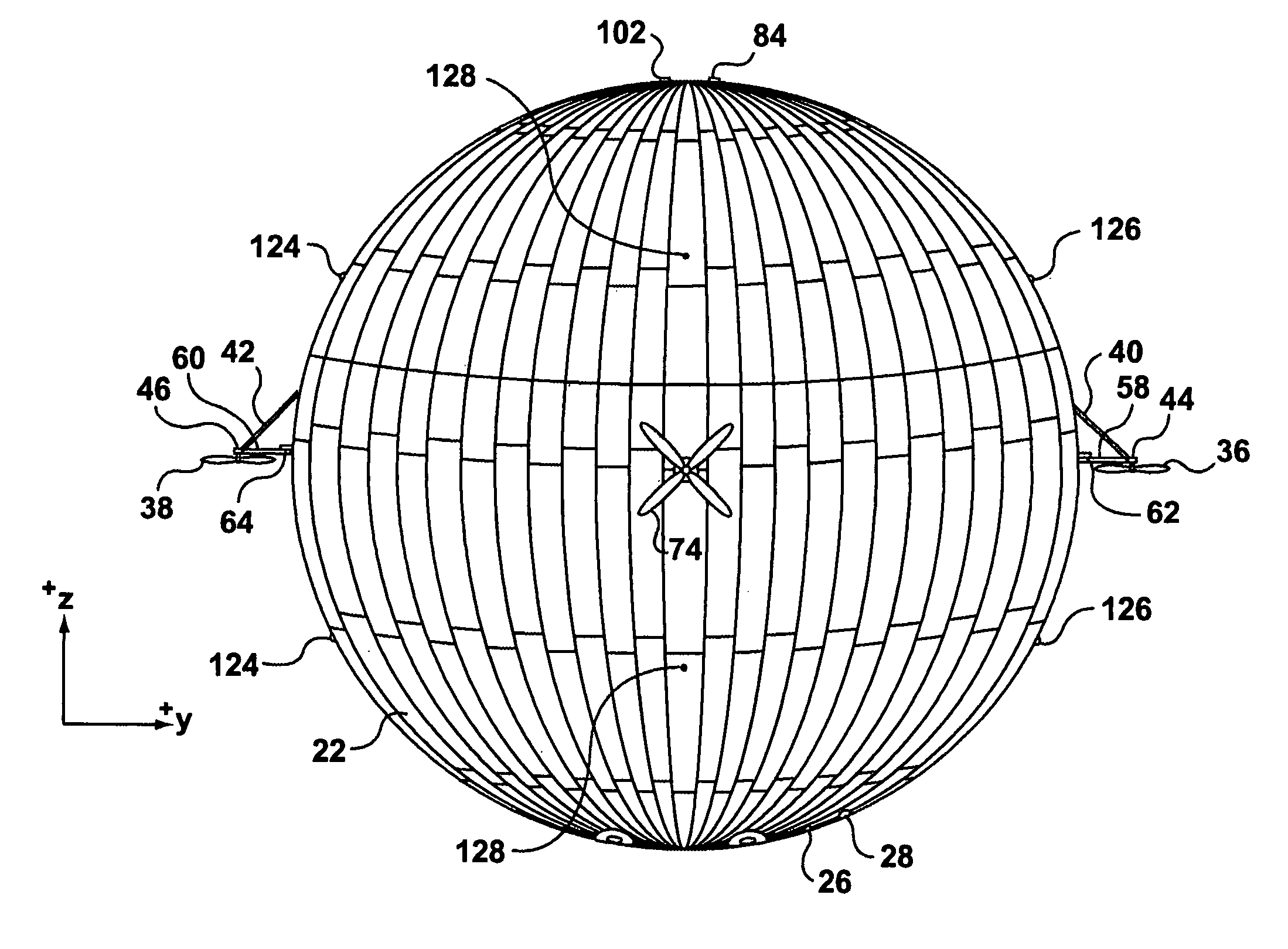
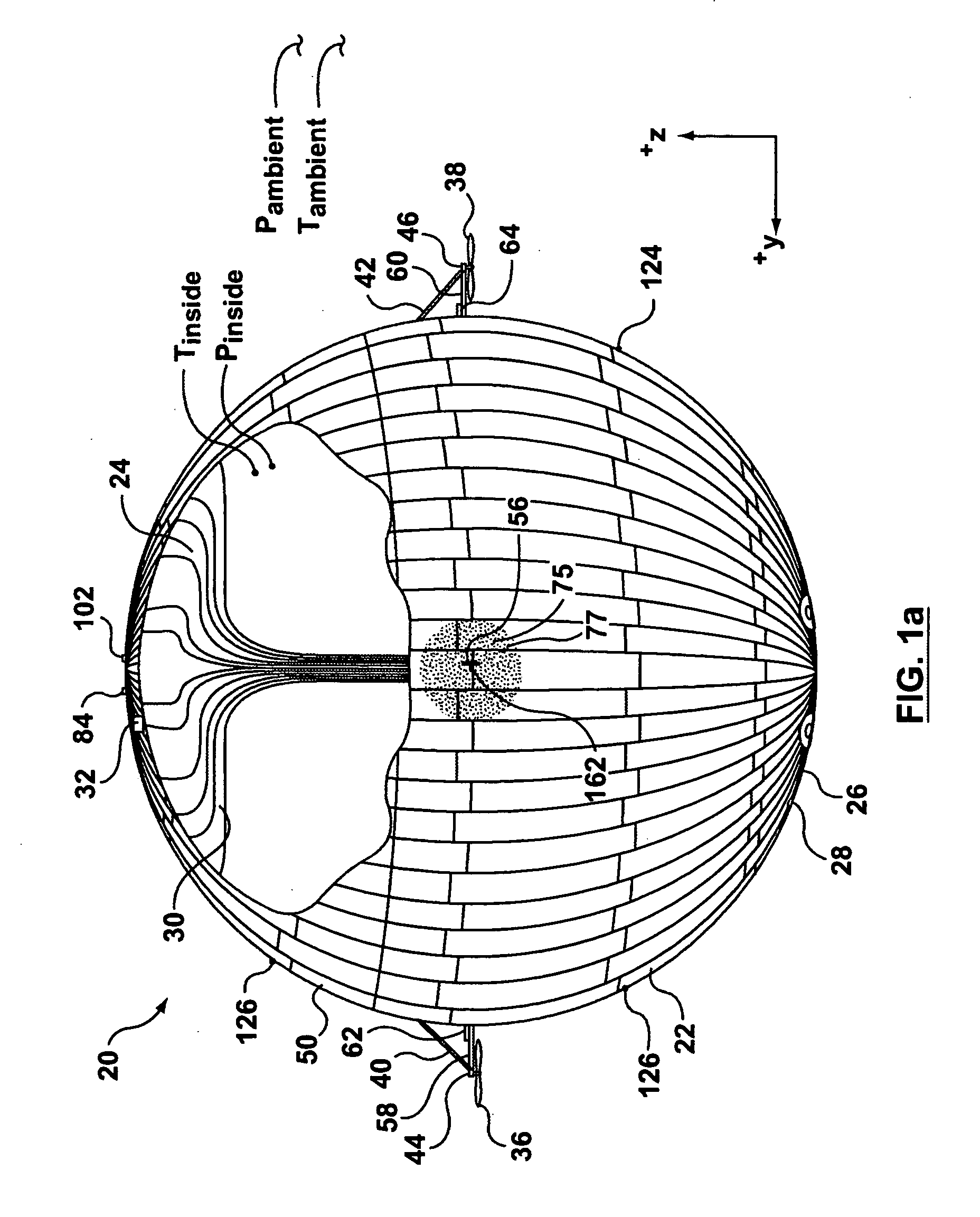
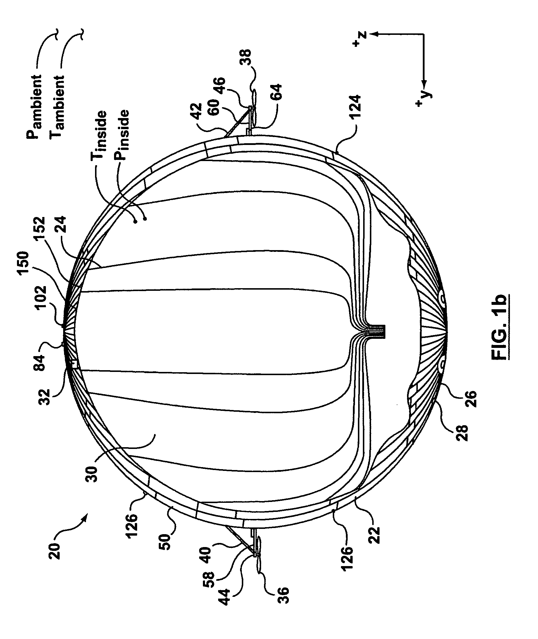
[0045]For the purposes of this description, it will be assumed that operating conditions are referenced to an ISA standard day, namely to a datum of atmospheric conditions at sea level on a 15 C (59 F) day. Also for the purposes of description, if the aircraft is thought of as having a vertical, or z-axis, a longitudinal, or x-axis, and a transverse or y-axis...


PUM


Abstract

An airship has a generally spherical shape and has an internal envelope for containing a lifting gas such as Helium or Hydrogen. The airship has a propulsion and control system that permits it to be flown to a desired loitering location, and to be maintained in that location for a period of time. In one embodiment the airship may achieve neutral buoyancy when the internal envelope is as little as 7% full of lifting gas, and may have a service ceiling of about 60,000 ft. The airship has an equipment module that can include either communications equipment, or monitoring equipment, or both. The airship can be remotely controlled from a ground station. The airship has a solar cell array and electric motors of the propulsion and control system are driven by power obtained from the array. The airship also has an auxiliary power unit that can be used to drive the electric motors. The airship can have a pusher propeller that assists in driving the airship and also moves the point of flow separation of the spherical airship further aft. In one embodiment the airship can be refuelled at altitude to permit extended loitering.

Description

[0001]This application is a continuation application of my co-pending U.S. patent application Ser. No. 10 / 178,345 filed Jun. 25, 2002, which application is hereby incorporated by reference herein.FIELD OF THE INVENTION[0002]This invention relates to the field of buoyant aircraft and operation thereof.BACKGROUND OF THE INVENTION[0003]In a number of applications it would be desirable to be able to provide a relatively stationary high altitude platform, hence the desirability of the present invention.[0004]One known kind of stationary high altitude platform is a geo-stationary satellite located 36,000 km above the earth. While a geostationary satellite system may have a large “footprint” for communications or surveillance purposes, this may be higher than is desirable for high resolution observation, and the development and launch cost of a spacecraft may tend to be very high. Non-stationary, or low orbit satellites are also known, but they are at any given point in the sky only moment...

Claims


Application Information

Patent Timeline
Patent Type & Authority Patents(United States)
IPC IPC(8): B64B1/00B64B1/02B64B1/32B64B1/34B64C39/00B64C39/02B64C21/02
CPCB64B1/02B64B1/32B64B1/34B64C21/02B64C39/024B64C2201/022B64C2201/042B64C2201/044B64C2201/101B64C2201/122B64C2201/127B64C2201/146B64C2201/165Y02T50/166Y02T50/10B64U10/30B64U50/11B64U50/19B64U2101/20B64U2101/30B64U2201/20B64U50/13
Inventor COLTING, HOKAN S.
Owner 21ST CENTURY AIRSHIP TECH
Why Eureka
Try Eureka